| Attachment | Size |
|---|---|
| 779.49 KB |
Hey everyone
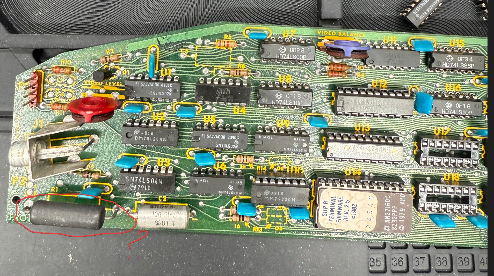
Sorry for the slightly obscure question — I’m working on restoring an Apple II "Sup'r Terminal" 80-column card.
By "restoring," I mean I've noticed that the board has several ICs that are known to fail over time, so I'm adding sockets for each chip to make future repairs easier — even decades from now.
While looking over the schematic, I came across a large power resistor labeled "R1." Its only apparent function seems to be loading the power rail — basically just burning off energy as heat. And it gets really hot. As far as I can tell, it doesn’t do anything essential beyond that, so I’m tempted to just remove it.
That said, maybe someone with more experience understands why it was included in the first place? Any insight would be appreciated.
When doing these kinds of repairs or mods, I try to distinguish between what was important in 1979 and what still matters in 2025.
Thanks in advance!
It's a cheap gambit designed to reduce the current draw on the +5V rail. Since this 33 Ohm resistor sits between the +12V and +5V rail, the current that flows through it and into the +5V rail is:
(12 V - 5 V) / 33 Ohms = 212 mA
This means that whatever current this card will draw from the +5V rail without the resistor, it will be reduced by 212mA when the resistor is there. It also makes the +5V that powers the card slightly more stable by "drawing water from two wells".
Btw, I don’t think there is a need to preemptively put working chips on sockets, especially if you care about the card's value.
Thanks a lot CVT, super useful feedback,
It's spreading the load on a voltage rail it's not really supposed to use - ok, makes perfect sense !
It is probably only a side effect of what the real old-time engineers accomplished ;)