Power Button Mod - Change the Stock LED on a G4
As part of a case mod, I wanted to switch out the green/orange LED behind the power button with a white LED on a Sawtooth G4. I looked around but didn't see any guides as to how it's done. It's a realtivly easy mod to do if you have basic soldering skills. This is meant more for the newbie but anyone can use it.
Here's what's needed:
Soldering Iron (30 watt; I tried a 15 and it didn't work very well)
Rosin-Core Solder (I used .032 diameter)
Desoldering Braid
One 5mm LED of your choice
Long flathead screwdriver
Needlenose pliers
Wire cutters
Please note: Any hack and or case mod involves a certain level of risk. There are several sharp edges inside the case which can cut through your fleshy bits quite easily. Additionally, you will be using a soldering iron which also makes a great accidental branding iron, house burning device, and eyebrow remover. So please be careful. Please understand that by undertaking this mod, you accept all risk and liability and understand that you could destroy a key component of your computer which may leave you unable to boot or use it.
With that said, let's get started.
Read all of the instructions first. Okay, stop laughing, reading the instructions does help especially if you are a newbie.
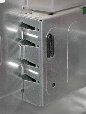
Unplug your Mac and open up the case. Behind the front panel and just below the middle, you will see two covers. The one near the middle is for the speaker and the lower cover is for the power, reset, and programmer's buttons.
There is a flat, 10-wire cable that on the far-side of the cover that connects the power button board to the logicboard. Gently pull it out. If you have trouble removing it, you can take the cover off first but BE CAREFUL. Use the long flathead screwdriver to push in on the tabs and move the cover towards the rear of the case.
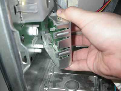
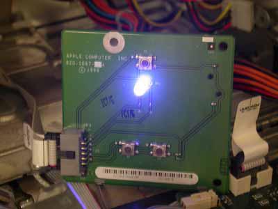
If you were not able to remove the 10-wire cable, you should be able to do it now. So this is the board that houses/controls the three buttons on the front of the case.
You will notice in the top right corner a small tab holding the board in place with two similar tabs along the bottom of the cover. Use the screwdriver to push in the tabs so you can pull out the board. Carefully, pull out the board. You may find that pulling out on the side of the cover will help loosen the cover's grip on the board.
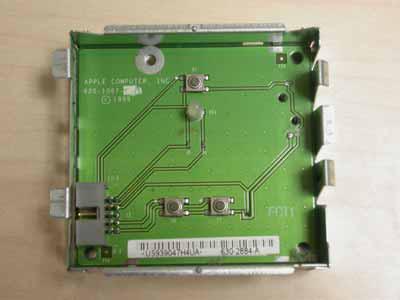
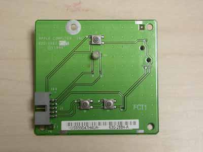
With the ten wire socket on the left and the single button at the top, flip the board over so that the back is facing you and the ten wire socket is on the right. You should also see a small fuse and holder on the left.
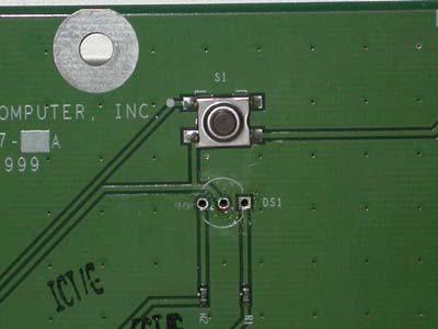
You should see three solder points just above center on the back, one square and two circles. These are the LED solder points.
Why are there three holes? I thought that LEDs had two pins. The LEDs used for the power button have two colors, green for power and orange for sleep mode. The middle pin is a shared pin.
Clear your work space of any flammable debris and plug in your soldering iron. Soldering irons get very hot which you won't realize until you're looking at the blister on your finger. Be careful.
Unspool some of the desoldering braid and place it over one of the soldering pads. I recommend using the needlenose pliers to hold the braid in place as it heats up quickly. Apply the tip of the soldering iron to the top of the braid and hold for a few seconds. (Try not hold it for too long because you will solder the braid to the board.) The iron will heat up the solder which will collect into the braid. Place a clean portion of braid on the aolder point and repeat until all the solder has been removed. Do the same thing for the remaining solder points. It doesn't really matter which one you start with, just make sure you remove as much solder as possible.
Flip the board over and desolder the left and right sodler points. Be careful so you don't damage the traces on the baord. If you can manage it, desolder the center pin. If you're lucky, you should be able to remove the LED with the needlenose pliers easily. If you're not lucky like I was, try and get as much solder off as possible and pull off the LED by gripping the pins and pulling. If you don't really care, just grab the LED with the pliers and yank. You'll most probably pull off the LED and leave a pin or two. You might also damage the board so be careful. Clear out any solder by using the desoldering braid and sodlering iron.
Grab your new LED and you will notice that one pin is longer than the other. Insert the long pin into the left hole and the short pin into the center hole. (The right hole is not used.)
Optional test: You can plug the ten wire cable into the socket and try powering up the computer. Your new LED should glow. Shut down the computer and remove the ten wire cable.
Time to clip the pins. Make note of which pin is the short one and which one is the long one. Adjust the LED so that it sits above the board, not on it, and clip the pins that they stick out just a few millimeters out from the board. Grab your solder and sodlering iron and solder the pins in place.
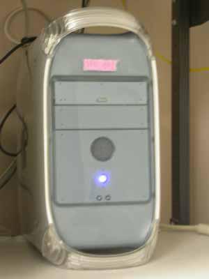
Reattach the cover to the board and connect the ten wire cable. Snap the button assembly into place on the front panel. Reconnect the cables and close the case. Get to a minimum safe distance of 3.5 miles and have a family member turn on the computer. Something will glow, the LED or your brother. If it's your brother, time to troubleshoot on the run. If the LED glows, congrats!
Revised 13 October 2004


Comments
cool
i really do like this. so simple yet so drastic. i could see this happening to an old imac. the only time i want to see orange and green is if the imac is tangerine or its an ibook plugged in. nice hack though.
err....ah...
Just curious, why not use a 2 color LED? You could change the color but still retain the 2 color functionality.
Easy...
Because 3-wire 2-color LED's are like white wales. try finding one, seriously. i can only find 2 wire(both colors at once) or 4 wire ones.
Although i suppose it would be possible to mod a 4 wire one...
been here? [url]http://www
been here?
http://www.maplin.co.uk/Module.aspx?ModuleNo=35840&TabID=1&source=15&WorldID=&doy=1m11
You could replace the LED wit
You could replace the LED with another bi-color LED but I have only seen them in green/red or green/orange variations. The system mod I am working on uses black and white as the only colors so the existing bi-color LEDs would look out of place.
Bi-color LEDs exist but you might not find them at your local DIY/Radio Shack/Fry's, you might have to go to a store that specializes in electronic components. Or just go online.
Use 2 LEDs?
:mac:
Why not just use 2 small LEDs?
The three 'holes' are just the two positives on each side and ground in the center. You just have to use an LED on each positive and have them share the ground.
:mac: