I bought this Sanyo VM-4209 and it has a slow, swervy picture that cannot be adjusted out. I've tried the front panel vert and horiz adjustments and the rear adjustments, but cannot get the picture to stabilize. I have downloaded and referenced the VM-4209 service manual. Anyone ever have a similar problem? If so, what needs to be done? I've included a couple of pictures of the internal circuitry so that a fellow Applefritter member can show me the area that needs attention/fix. I have experience reparing computers, but not much experience fixing video monitors.


Looks like a ground loop on the video input. I'd start by feeding in a different signal (e.g. from a VCR) to see if the problem persists. Try a different cable as well. If that doesn't help, then move to the power supply to see if there's excessive ripple which would indicate bad filter caps.
I know that failing capacitors can cause some kind of geometry issues. In these old CRTs there are a number of old electrolytic caps which are drying out over time and loosing their capacity or short out. I know your nice vintage monitor has a high value and is worth to get a whole recap to make it future proof for the next 20 years or more.
+1 for either full electrolytic recap, or one at a time until the problem goes away.
Yes, filter caps likely going bad...
I have same issue. No ground loop found. It should be another way to fix it without replacing all the caps. Any other solution ?
Have you inspected all the caps? Often the bad one is obvious because it will show signs of leakage or bulging. But not always...
what would be an excessive value of ripple voltage ? mine is aroud 2 vpp
IMG_4531.jpg
the image is kind of slow - wavy..start from the bottom of the CRT to the top. Looks like an internal signal on the top of the input
That brown goop on those caps sure shouldn't be there... Figure out where it came from and that might just be your problem...
pulled the cap and measured and showing labaled value. Caps looks good. Still seeing that vawy image.
That might not be where it came from. It might have dripped there or come from the other cap. Hard to tell from that pictture.
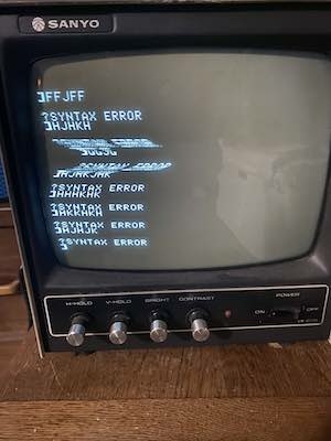
The monitor works but there are slow moving areas of horizontally display that start from the bottom of the screen, slowly move to the top, then restart at the bottom.
Here a picture. Igonre the dark area ..just notice the character lines...looked for ground noise and ripple. Caps seems to work well. Any suggestions ?
IMG_4538.jpg
That is classic 60 Hz hum rolling through the picture. It can be caused be either an external signal riding on the video input or due to poor filtering somewhere in the monitor. The first step is to use a different video source (e.g. VCR) and a different cable. That's the easiest way to see if the problem is external to the monitor. If not, your best bet is to use a scope to find the bad part - most likely a capacitor. If you don't have a scope - and you don't see any obviously leaking, bulging, or discolored caps - then you can try adding a good cap in parallel to see if it gets better. Or, as some here will suggest, just shotgun all the caps and hope that fixes it!
I tried a different source/ cables and had same issue. Agree wiith you, definitely is the monitor with a 60Hz hum. I can see it with my osciloscope. Just trying to find from where it is coming from. I also have pluged both equipments , the monitor and my PC in the same power outlet.
Now I need to try from where this 60Hz is coming from. I check visually all caps and they seem to be good. I am adding a cap in parallel to check as well. Thanks for your suggestions .
If you are in North America, it's pretty clear where the 60 Hz is coming from. I would replace the electrolytic caps, starting with the ones in the power supply of the monitor. 95% of the time bad caps visually look perfect.
I have puller one -by -one all electo caps and tested with a fluke meter , all showing good. Do I still need to replace them even Fluke is telling me they are good ?
What type of meter is it and which of the capacitor's parameters is it measuring?
It is a Fluke 87 V - with a built in capacitor meter.
Can't find a bad capacitor just by measuring its capacitance. With this meter you can only detect if it has shorted or gone completely open, but that doesn't happen often. What you really need to measure is its ESR, preferably at or near its operating voltage.
I fully agree with CVT. Very often the capacitance is still ok but the ESR value far off. I don't understand why to solder back in an old 0,x Dollar capacitor?
OK, I will try and get a ESR meter,
Probably not your issue, but I do notice that you have the video input termination set to Hi-Z instead of 75 ohm. Might want to see if that changes anything...
Good catch! Mismatched impedance could definitely cause a wavy picture. Even if the switch set to the 75 ohm position, I would still measure the resistance across the input to make sure the switch itself is making good contact, which is just connecting a 75 ohm resistor across.
I have found capacitors C616 and C508 that has gone bad. Replaced both and now monitor looks good. My monitor is a Sanyo VM4902 . Thanks all for your suggestions !!
Cool. Great news. :-) Can you please share your findings? Did you measure these caps again?
IMG_4544.jpg
Great! This is very encouraging. I, myself, tried a different source, a DVD player, and saw the same slow wavy picture. I tried moving some of the interior monitor wiring around a litte with a wooden stick and was not able to find any area that caused a noticeable change. I, next, enabled the Videx Videoterm video output on my Apple II plus and saw that with 80 column mode selected the wave on the picture was a little slower and not as bad as when 40 column mode is selected. I thought that was interesting -- not sure I understand why that is happening.
Seems like the next step should be replacing capacitors. I do not have any capacitors on hand right now. There seems to be a few different values and types used in the monitor. Should I just use the parts list shown in the VM-4209 service manual and order all of the electrolytics? I'm thinking I should start with the electrolytic capacitors in the power supply area as well as the C616 and C508 that was your solution experience ( I understand that it is possible that these may not solve my issue, but it is worth a try). Where do you purchase these electro caps? Mouser Electronics?
The reason that the wave moves from the bottom to the top of the display is that the 60 Hz hum is slightly faster than the vertical rate of the video signal (59.94 Hz for true NTSC). Whether coming in externally or caused by faulty filtering in the monitor, this distortion occurs at the AC line frequency which is nominally 60 Hz in the US and other places.
The vertical rate of the Apple II 40-col video is based on its master clock oscillator which runs at 14.31818 Mhz. The 80-col board has its own oscillator and video generating chip so its vertical frequency would be close but not exactly the same as the Apple video. Thus, the wave could move through the picture slightly faster or slower.
Now, I am trying to understand why letters at the top of the screen is showing bigger than the ones at the bottom ...any ideas on why ?
IMG_4546.jpg
Some monitors have a trim pot inside to adjust for things like vertical and horizontal linearity. It is also possible that you've got another capacitor somewhere that is slightly out of spec. Maybe some other part. Even sometimes resistors can get out of spec over time.
Looks like this monitor behave like this ...adjusted the vertical pot to "compress" the image a bit and here is the result:
IMG_4548.jpg
Doesn't this monitor have a separate vertical linearity potentiometer?
In the schematics of the VM4509 this is VR501, also labeled V-LINE: https://www.applefritter.com/comment/92430#comment-92430
That's exactly the thing I was thinking of in message #32. It is common for there to be V-LINE and H-LINE trim pots, but they are often inside and not on the front panel since they normally don't need to be changed. However, replacing caps or other components can require them to be tweaked.
Normally the front panel H and V knobs control size mostly and not linearity.
I tried to order the replacement capacitors for C508, 2200 uF 35V, and C616, 0.1 uF 630V. I ordered them from Mouser and they are the correct values, but the physical size is smaller than the originals.The 2200 uF cap is about 1/3 the size of the original one. I've added these capacitors in parallel with the existing ones and I do see improvement -- only a small amount of wave on the monitor picture so I think I am on the right track. I'd like to get replacement capacitors that are closer to the physical size of the originals before I solder them in.
Kalustian: Were you able to find C508 and C616 replacement capacitors that were the same physcial size as the original? If so, where did you get them?
Electrolytic capacitors have shrunk in size since the 1970s as all electronics have miniaturized, and the manufacturing process has been more tightly controlled. Having smaller cases is not usually a problem, but the lead spacing is critical and should be maintained. If the leads on your replacement components are not the correct spacing for the circuit board, there is a prescribed method for dressing the leads, but by no means should they be carelessly bent as this can compromise the rubber bung. The method involves round-nose pliers and lead-forming templates.
I always measure lead spacing and use it as a search criteria when purchasing replacement components.
Many times you can find a replacement capacitor with a higher rated voltage that is the same size (or at least the same lead spacing) as the old failed component. Most of the time this is okay, but there is a school of thought that the rated voltage should not be increased too much: more than 1.5x the original rating. This is because the dielectric layer is more prone to dissolution into the electrolyte when caps are used far below their rated voltage. This is more of a theoretical concern.
New caps may also be found in larger sizes if they have a longer lifetime rating. The price of 105°C, 5000 hr rated caps is usually not too expensive and there is little point trying to save money on devices with shorter life ratings.