I'm building a board which uses a few SMD parts. The resistors are no problem since the direction they are installed doesn't matter. They're a PITA to solder, but I can get it done.
The question is, which direction do SMD diodes go? The markings aren't 100% clear to me on the diodes and even less so the markings on this board.
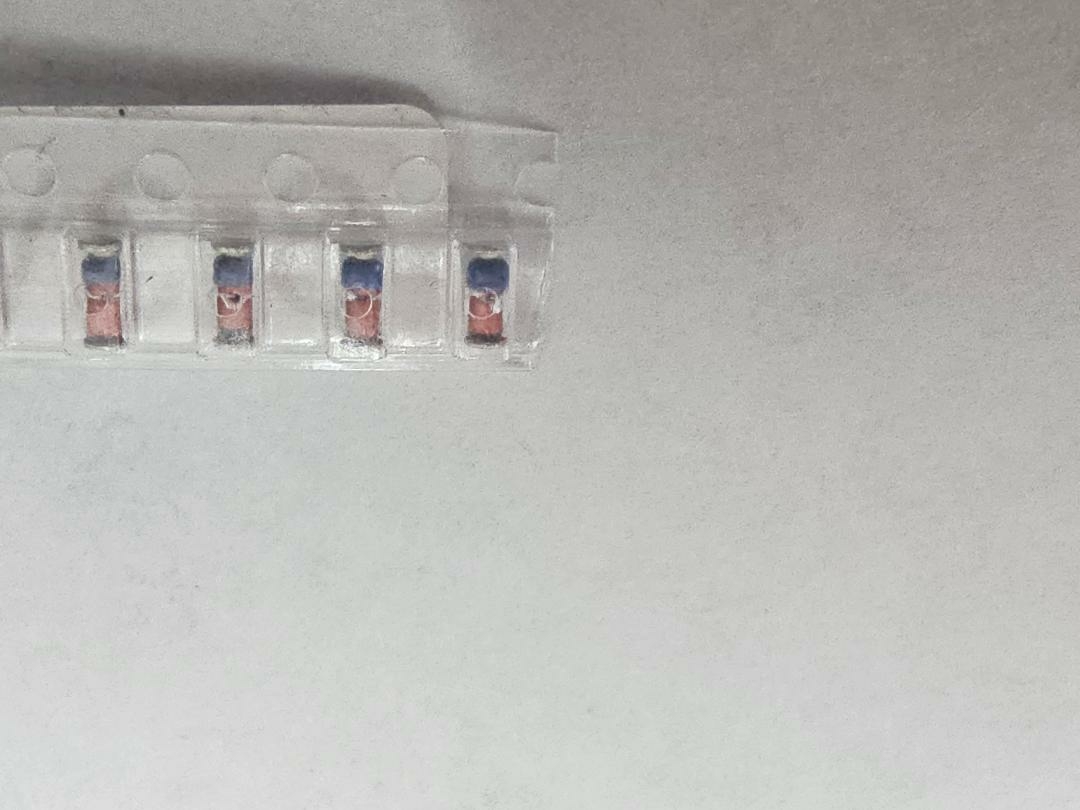
Here are the diodes, I am assuming that the smaller blue end is analogous to the stripe on the end of a through hole diode:
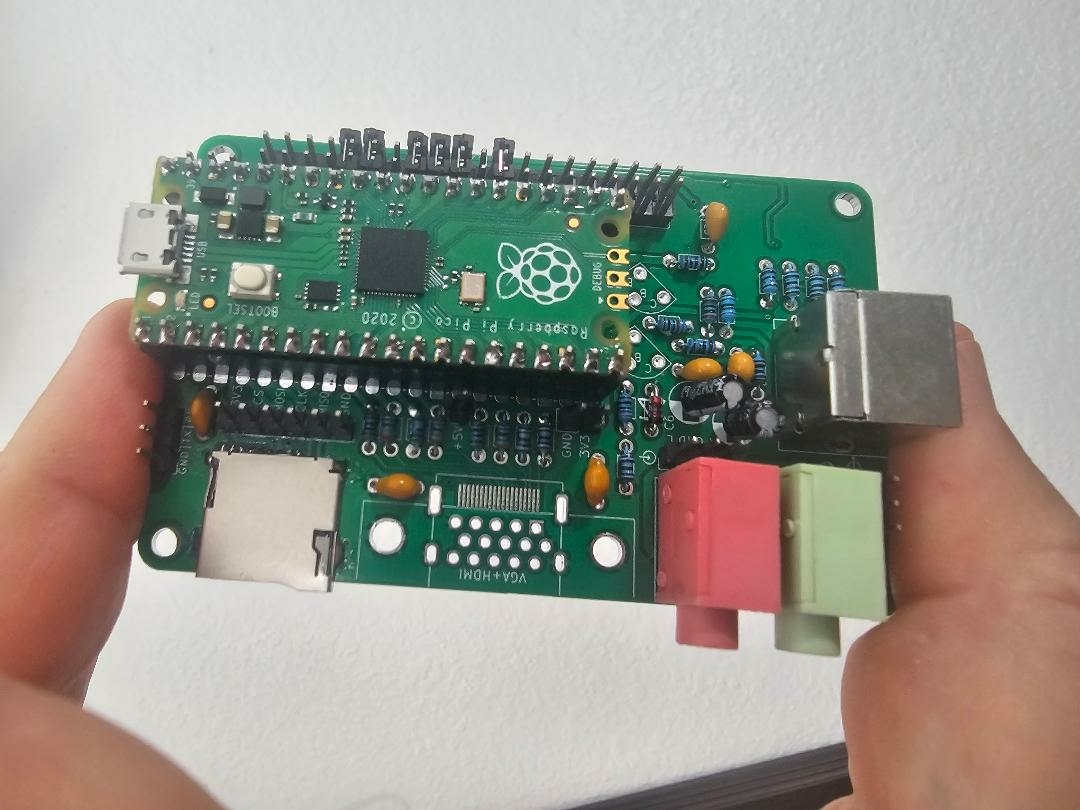
This is the board they are going on:
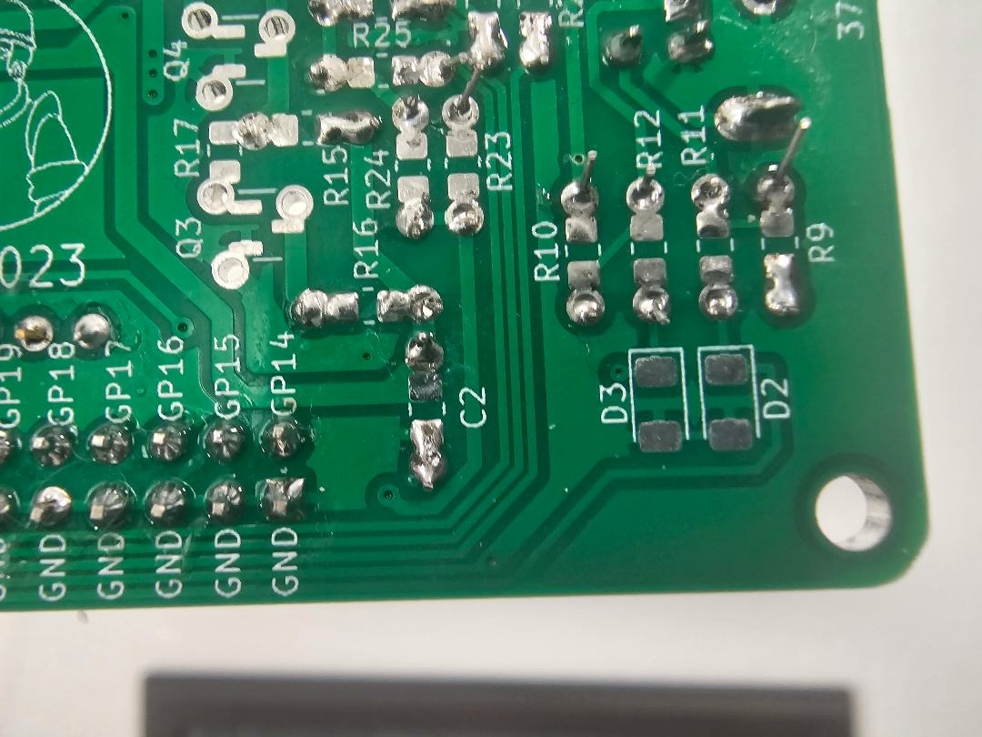
Here is a closeup of where the diodes go. I'm not sure which way to put them on. I am thinking that the sort of T looking symbol the perpendicular line is the direction the stripe (blue part) of the diode goes?


... if in doubt, is best checked with a multimeter, too. Even the really cheap and crappy ones from Harbor Fright (pun intended) have a "diode" test setting where you can see the forward voltage of the diode. Then, the red probe wire is anode, and the black probe wire is cathode. Which, normally, is the ring on the diode body. But better safe than sorry ! There are lots of SMD diodes in plastic packages where the cathode is a laser marked bar on one side, but the success of that laser marking process varies and it might be almost illegible.
The "diode" setting on a multimeter can also discern between PN junction and Schottky diodes, the latter have a much lower forward voltage. Same for Germanium PN junction diodes, but these are exceedingly rare nowadays. Back in the day they had special Germanium diodes for crystal radio sets which only had a forward voltage of 0.2V or less.
Any hobbyist shoud have a bunch of these cheap multimeters with diode and transistor "hfe" test settings. These are really useful in daily lab work. And even the cheap ones are precise enough for typical hobby work. It is rare that hobbyists need to measure voltages or currents to five or six digits.
The super cheap Harbor Fright (pun intended) ones, better avoid. They are still as precise as all other cheap multimeters, but their mechanical construction is poor, the PCB is somehow squeezed to the LCD contacts via a zebra rubber strip, and after a while of tossing them around you lose segments in the display.
- Uncle Bernie
Thanks for the explanation on how to measure the diodes with a meter. I do indeed have a few of those cheap Harbor Freight meters around, they used to give them out free or nearly free with coupons from their mailings. I also have a couple of at least slightly better meters, including an ancient Beckman Circuitmade DM10 I bought back in the early 1980s. I really need to probably buy something really good like a Fluke. I've always wanted one but for whatever reason never have sprung for it. I really need to do that and buy an oscilloscope. I can't afford a really good one like a Tektronix but there is a 200MHz dual channel one I am looking at which isn't stupidly expensive, around $400.
What I am still not sure about is the markings on the board. I guess I'm going to have to follow the traces on the board and figure it out from the schematic. It is clear on the schematic which way the diode needs to go.
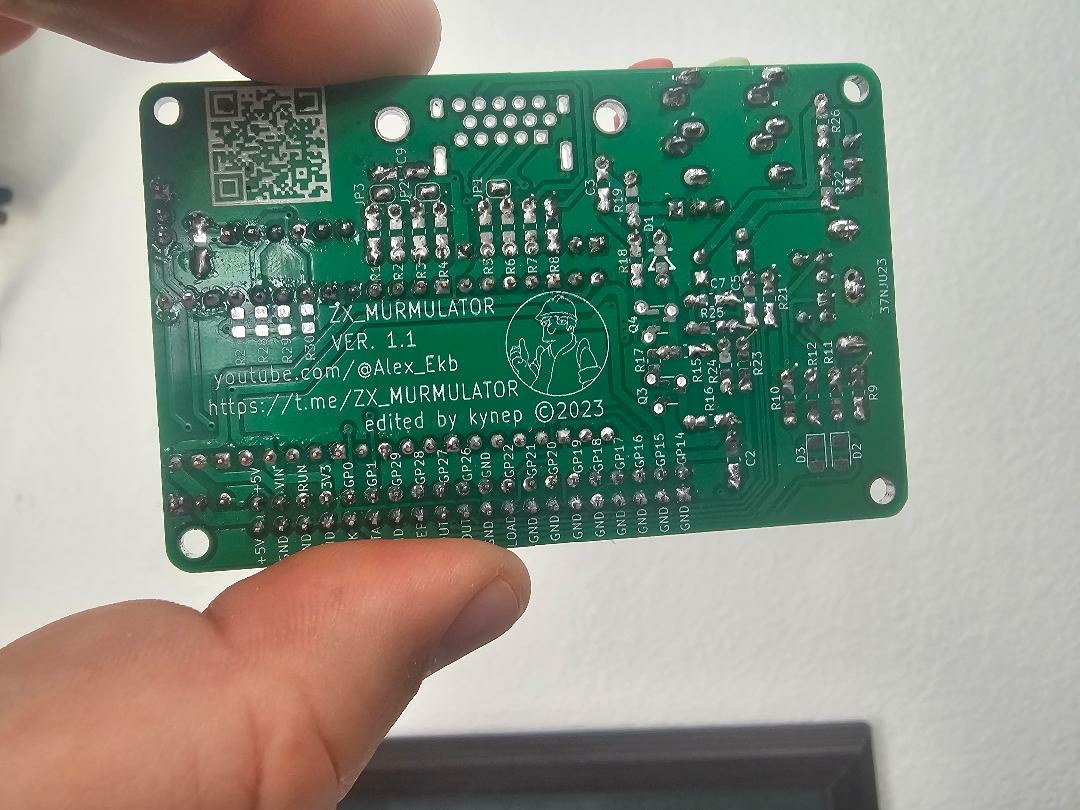
OK... crisis averted... I found a pic of the bottom side of an assembled board on one of the Russian sites.
photo_2023-09-22_16-.jpg
In post #3, softwarejanitor wrote:
"I can't afford a really good one like a Tektronix but there is a 200MHz dual channel one I am looking at which isn't stupidly expensive, around $400. "
Uncle Bernie warns:
Don't.
Don't buy any vintage Tektronix scope in any shape or form at any price.
These are notoriously difficult to repair.
In many cases, the hybrid modules for the XY plate amplifiers are damaged or bad, and these are unobtainium (other than taking them from another Tektronix scope of the same type, which works, makes no sense to do that).
Don't ask me how I know (I have about half a dozen Tek scopes in various states of disrepair and despite the service manuals are available online, I never succeeded to fully repair one. They then go back to their graveyard in my basement, and when I'm bored and have nothing else to do, they may reemerge from their grave, move up to my lab, just to haunt me and steal my time again).
- Uncle Bernie
P.S.: the older Tek scopes before the hybrid modules are a mix of transistor / tube circuits and the issue with them is the rot of the sockets they used for all the tubes and all the transistors.
I worded that terribly badly. The $400 scope I am looking at is a newly made Chinese one. Sadly, $400 Tekrtonics are usually used, old and probably will break down soon as you mention. And usually aren't going to have anywhere near the features -- when I was looking I didn't see any 200MHz dual channel Tek scopes for $400.