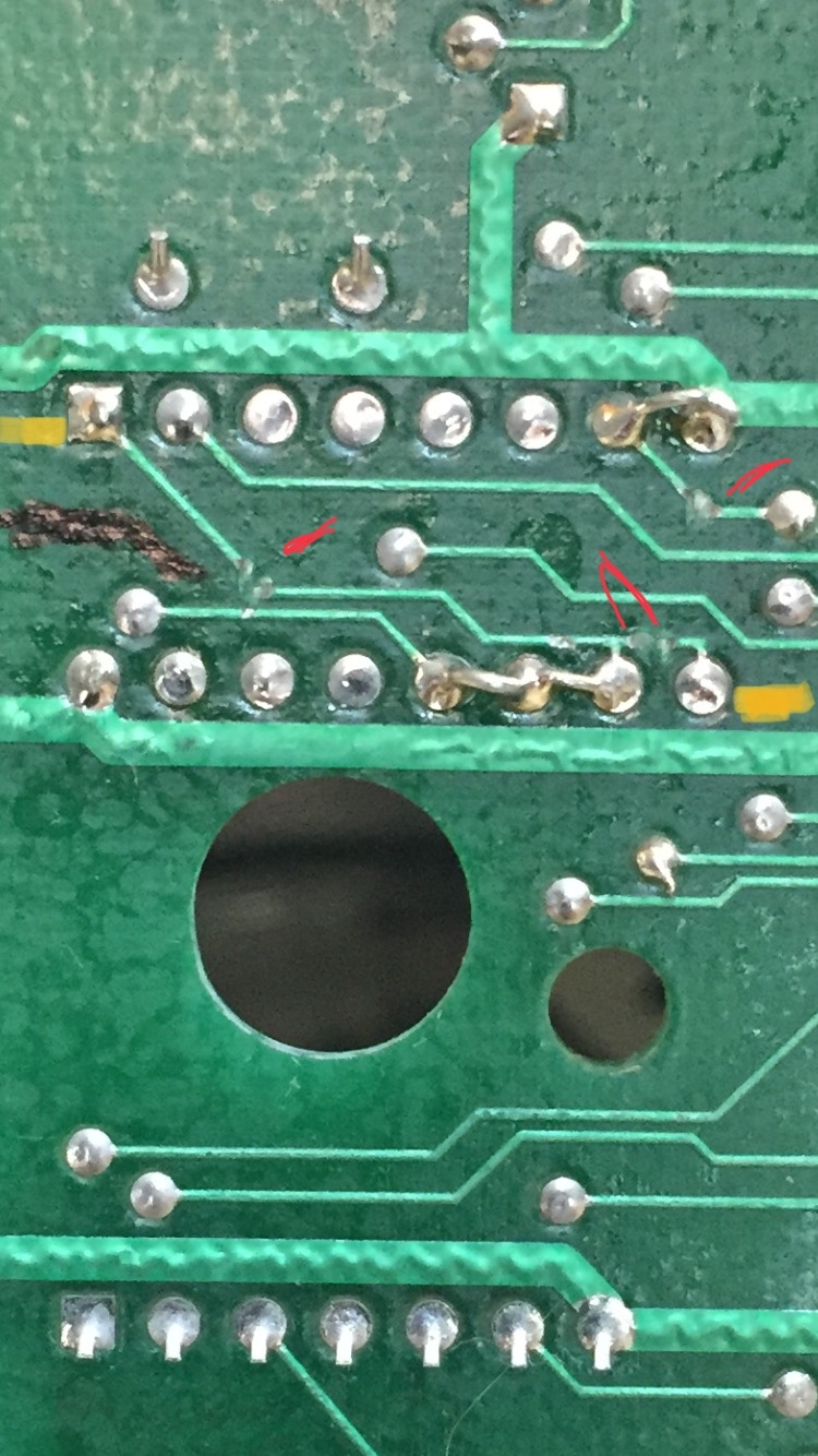
I have 2 iics. Both were working and now one isn’t. But my question in this thread is the board that isn’t booting has a 1.843200mhz crystal at location C6 where it’s clealy marked on the board there should be an LS161 there and the other board has the LS161 as it says. There are traces broken and pins jumped around the crystal. I looked at a PAL board (mine is an NTSC) and his had the same crystal there and his traces were broken and jumped exactly like mine. The only thing my board has that his didn’t is mine has a low ohm resistor coming off one of the legs of the smaller of the two HALs. Does anyone know why this was done? I was planning on removing the crystal, repairing the broken traces, removing the resistor on the HAL and installing an LS161 like the other board, and like the silkscreen says. But I’d like to know why this was done.
Thanks


The original motherboard used the LS161 to create a clock for the serial chips from the 14M master clock (dividing it by 8). This is not close enough to the 1.8432 MHz that the serial chips need to generate precise serial baud rates. So the 161 was replaced with a crystal oscillator in the later revisions.
You should probably keep it this way, especially if you ever plan to use higher baud rates.
Thanks for explaining that to me Jeff. Seeing the PAL board having the exact setup as mine plus the fact that the board was working briefly also led me to think I should probably leave it alone. I was just curious why it was done.
Thanks