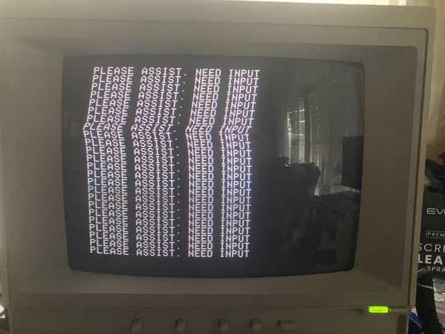
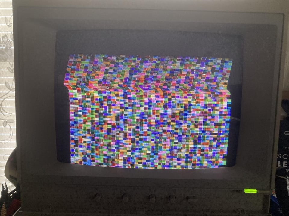
recently I recapped my monitor because it was experiencing so snow. But somehow in the process, it developed these odd geometry issues. I checked the polarity and values of all the caps and they are correct. The h hold control is a bit jiggly, it causes the screen to jump with you wiggle it. I tryed deoxiting all the pots as they were very scratchy. I was told I should try a new composite cable, which I did and that improved nothing. I checked the values on the filter caps with a capacitance meter and the largest c902 is supposed to be 680mf 200v but it's only reading 611. I checked another new one for reference and it's only reading 609. So maybe that's within tolerance? The second pic I have the v hold tuned all the way up and I set I'll can't center it, and when it switches back to text mode it loses hold. I'm really inexperienced with troubleshooting and not sure where to go. I ordered a nichichon replacement for the large cap just in case.
Anonymous
User login
Please support the defense of Ukraine.
Direct or via Unclutter App
Active forum topics
Recent content
Navigation
No Ads.
No Trackers.
No Social Media.
All Content Locally Hosted.
Built on Free Software.
We have complied with zero government requests for information.
A 680 µF electrolytic is normally supplied with a 20% tolerance. That means plus or minus: as low as 544, or as high as 816 are still within spec. Elcos with 10% tolerance are available in some limited series, but for power supply purposes that's unnecessary.
In the pictures you posted above, does the "bump" move steadily up from bottom to top, or is it fixed in place?
The image stays in place. It doesn't move. It's like it's losing synch at the top 1/4 of the screen. i can get the bump to move ever so slightly worth the v hold control, but there's not much play and it definately won't center without losing synch. I could adjust the v center to move the image up, but that's on the board under the neck so it's difficult to reach and I'm not certain that would do much as it was never changed and it worked before the recap.
If before the recapping the geometry was perfect, then one of the new caps is bad, the wrong capacity or connected through a cold solder joint. If you kept the old caps, you can start replacing them one at a time until the issue disappears. If you didn't, you can still do this with the new caps you ordered.
The important thing is to never do a full recap on a CRT monitor in one step. Instead do it in groups of 3 or 4 at a time and then check that the situation has not gotten worse before you move on to the next group. Doing it this way allows you to easily backtrack. On several occasions I had to leave an old cap in place, because changing it made things worse.
Blind recapping is lamer's trial and error approach be it in groups or not without understanding. A lot of vintage caps of that Apple II era still perform quite well.
That's true, at least the larger ones when they have reformed. The 0.1 to 22 µF electrolytics are the ones least likely to still be wet after 40 years.
The geometry problem shown is not pincushioning, but has some similarities. It causes the horizontal deflection to fly farther left during the horiz blank period, but only when in the vertical center (when the current in the vertical yoke coil is near zero). There is some path for vertical and horizontal drive to interact (characterizing most geometry adjustments) requiring adjustment to null out this effect.
I guess I'll pull each one out one by one and check them on the meter. It's not a cold joint, I visually verified each one and reflowed any that even remotely looked bad. Unfortunately there's just not that many people around that fix these things so I had to take it on myself. I had no schematic and little experience so I had no way to know which one was causing the snow. So I bought a recap kit from console5.
This may be your problem... but also may not. And it's not really a console5 thing but more a modern cap thing.
When these monitors were made different tollerances were in play. For example, with power supplies tolerances are usually -10/+100 which means the under 10% is the important one. Power supplies having double the capacitance is often benefical because most caps are just banking power. If timing was critical the tolerance would be +/-1,5,10% depending on the application.
But today, caps are pretty much -/+20% across the board as is likely the case with the caps in that kit. Great brands, but there was not any attention made to the series and the application. Most may be generic use which may or may not be good for special uses like switching power supplies, or CRTs. Finding different tolerances today can be tough. If it were me, I would have checked all caps in the kit to verify they conform to a -10% tolerance. If not, I'd replace. I'd also check the series and pull the mfg data sheets for that series just to confirm there isn't something being used in a way the cap can't handle. As an example, general use caps may not be able to handle high ripple found in SMPS so a general use cap may be overwhelmed by the ripple. Or maybe the impedence is too high/low or ESR too high/low for how it's being used in the CRT.
I'm with everyone else that suggested rolling back one/group at a time and see if you can isolate what's causing the problem. From there you can decide what's the best next move.
Stay safe in that CRT, those can be dangerous and the flyback can recharge after discharged which can be quite a shocking discovery!
Does this monitor have correction magnets on the yoke?
If so you probablre disloged, rotated or knocked off one of them.
I'm sure it does, but would that cause only the top 1:4 of the screen to lose horizontal hold? Seems like that would cause alignment issues.
And I didn't save the old caps, there was nearly 40-50 of them and I wouldn't know where one or the other originated from anyways. I've got three ideas atm (1) try to adjust the v center since it's obviously not centered and hope the dent is just the picture almost losing hold cause it's at the extreme edge (2) try replacing that large out of tolerance cap c902 (3) pull them one at a time and check them in the capacitance meter. (Which will also serve as reflowing them). Other then that it's back the the drawing board.
This is definitely not the case. It's impossible to produce this picture by manipulating or removing any of the magnets.
- Does the monitor show the same symptom when using another video source (like a VHS player, video game console, TV test picture generator) or did you test it only with the Apple II itself ?
- Can you change the shape of the "wave distortion" by manipulating H-HOLD ?
- Can you move the location of the "wave distortion" up and down the screen by manipulating V-HOLD ? (Try to get a picture that slowly rolls up or down and note if the distance of the distortion to the beginning of the field - the back horizintal bar made by the VSYNC pulse - changes or not).
Just asking for easy checks I'd do before speculating about what went wrong during the recapping.
- Uncle Bernie
I can manipulate it with h hold. It won't dial in though. It goes past good to the wrong direction. Iit moves slightly with v hold, but it quickly loses synch. There's not much play and it won't center at all. It goes out of synch before it gets close. I took it apart and adjusted the v center and now the Apple ii logo is off the top of the screen, but I can get it right with v hold jiggering. But I can never get the graphic right. Also Apple ii looks A bit off to the right. I actually oddly enough don't have anything with composite out except an old famicom, but it's also on the work bench cause someone used the wrong pole adapter on it and I have to replace the diode. But I don't think it's a source problem as it worked fine before and I didn't mess with the Apple ii at all.
As far as the roll, the distance remains the same it just moves around. So idk. I really wish I could find a schematic. Btw it's the Samsung version not the hitachi.
Any chace you tried to clean the pots? If you did, did you use a contact cleaner like deoxit d5 on any of the pots?
Ok, so I reread the OP, and my previous question is changing to did you use Deoxit d5 or Deoxit FaderLube on the pots?
I used fader lube. It improved them quite a bit.
Awesome! Wanted to make sure you didn't use d5 and unknowiningly potentally destroy the pot in the pocess.
I am expecting they are linear so a big change with small twist is confusing and may suggest a replacement may be in order. Easy to find one to test with, but finding one that would work in that design may not be possible. I guess it's also possible someone before you tried to fix and sprayed the pot with something they shouldn't have which could also explain the overly sensitive response. To rule them out, could check the response with a meter to confirm it's smooth and linear.
I doubt they were ever serviced since before I did it, they were practically locked. But personally, I also believe there is something wrong with that v hold pot. I've seen Adrian use qd cleaner followed by fader lube on them, but I didn't do that.
im afraid I may have put pressure on it when I was doing the recap since it's on the back of the board. I don't honestly think anything's wrong with the caps. But I could be wrong.
In post #20, 'Jonweimer' wrote:
" I'm afraid I may have put pressure on it when I was doing the recap since it's on the back of the board. I don't honestly think anything's wrong with the caps. But I could be wrong. "
Uncle Bernie comments:
A lot of things can go wrong when working on decades old PCBs, especially when these are not the epoxy/glassfiber (i.e. FR4) type, but the phenolic resin soaked / baked paper type, which gets brittle and has inner mechanical tensions, which than may lead to hairline cracks in the traces. I have one nice Shibaden B&W monitor from the late 1960s which has all too many hairline cracks but otherwise would work fine. So it's not necessarily a wrong capacitor.
What the pictures you posted (and the results from the V-HOLD and H-HOLD tests I proposed) hint at is a problem with the lock-in of the horizontal oscillator. The Apple II produces a non-standard video signal with a non-serrated VSYNC impulse. There may be one lonely pulse inside the VSYNC, IIRC, but I don't remember the details, and don't want to whip out the oscilloscope to look. This absence of horizontal sync pulses during VSYNC causes the horizontal oscillator (which actually is a sort of PLL) to lose lock, and what you can see on the screen may be its its attempt to get into lock again.
Now, with the monitor being an Apple product meant for the Apple II (if so) it should be more tolerant to the nonstandard video signal, we should think. But this typically means, unless the deflection system is fully digitized, which I think is unlikely (these digitized TV chip sets still for CRTs were done in the 1990s), that the horizontal oscillator must be adjusted to a much tighter tolerance than in a standard TV, so it does not lose the phase lock to the horizontal sync frequency too badly to recover quickly enough. Any change of the critical timing components for that process may get this out of whack and then you get the symptoms seen. Note that a change of the supply voltage for the flyback transformer may also have an effect because the voltage determines the current ramps in its primary windings. In usual TV circuits this is compensated for by changing the ON/OFF time of the horizontal output stage transistor, and this compensation also may entail some capacitor you may have changed, so the carefully adjusted circuitry is now out of whack.
What you can do to rule out any other reason is to apply a video signal which has a serrated VSYNC, and most video game consoles had that, otherwise, people would have seen that ugly lock-in slant in the picture and brought it back to the dealer for a refund. BTW, the Apple-1 video signal is even worse non-standard, and ironically, the rejection of the Apple-1 by Hewlett Packard where Woz was employed at the time was largely revolving about the infeasibility to guarantee that the Apple-1 would work flawlessly with any household TV or household cassette recorder. This is why the policy of Hewlett Packard at the time (like with many other computer manufacturers) was to provide all system components from "one hand" - themselves. So, Woz had done his legal duty (offering the Apple-1 to his employer) and because it was rejected (they could have bought the rights for peanuts) Woz was able go forward and found his own company (together with Steve Jobs). Without that rejection, Apple (the corporation) would not exist. What a ironic twist in history. And, the concerns of Hewlett Packard about the possible incompatibility with random household TV or household cassette recorders was justified. It was a disaster: the technical support phone at Apple rang off the hook and only Woz could help the Apple-1 owner. And this is the root of the management decision to "buy back" the hapless Apple-1. The rest is history ... but now back to the main topic.
True TV professionals would use a test picture generator to adjust everything in the TV.
I would think that without the service manual (or at least a schematic) for this monitor, your chances to fix the issue in a useful amount of time are slim. The more you experiment and turn trimmers inside the worse it may get (the change of H-HOLD and V-HOLD I suggested is harmless as it easily can be seen on the screen where the correct adjustment is).
So try find a service manual / schematic before you go any further.
- Uncle Bernie
From what I've read a schematic was never published and it was only an internal Apple thing, and lots of people have complained that they haven't been able to find a third party breakdown for the a2m6021. So I'm probably screwed in that department. I'll try checking the caps and replacing any that are crazy out of tolerance. That one filter cap for example is a bit on the high tolerance side. But outside of that, I'll prolly end up taking it to an electronics repair shop and try to find one with an old timer. /sigh
the only internal pots I can locate are v center, h phase and ColorSynch. And i cranked the v center way up to try to get the graphic more centered and that didn't work well.
I found one schematic for the a2m6021 but none of the stuff lined up with mine so it must be for the hitachi.
Would dialing up the values on the fly back do anything? It has those two adjustments. I think it's mainly just raster and focus though.
In post #23, Jonweimer wrote:
" Would dialing up the values on the fly back do anything ?"
Uncle Bernie recommends:
Don't touch these adjustments. Anything going wrong there may affect the high voltage for the CRT anode and this may have disastrous consequences.
Oh, and don't waste your time and money bringing that monitor to a repair shop. Without a schematic, they can't do anything, and still may charge you for their time.
The best thing you can do is to find a good video source with serrated VSYNC. If the problem is gone with it, you know what is wrong. And then you could trace the horizontal output transistor base back to some circuitry which - hopefully - is based on some IC, most likely, a Japanese type, which contins the horizontal oscillator and all the horizontal sync circuitry. Then try find the datasheet for that IC with the application notes, which typically show the external circuitry for the IC and explain how everything works. Based in this, you should be able to narrow down the candidate components which may cause the trouble to a few.
For any other root cause for the problem, all bets are off.
- Uncle Bernie
Only the Rev 0 Apple II motherboard lacked vertical serrations. That is why most monitors would have the flag waving at the top of the raster. This was fixed in all later revisions including the IIe.
Methinks the issue could be the result of his recap. Some monitors are known to have the wrong polarity marked on their PCB (although I have no knowledge that this monitor did). I hope he checked the orientation of the original caps before removing them.
Sadly I went by the board markers. But to be fair I think if it was multiple caps it would be showing a lot worse image then it is, it any. It's probably just one wonky cap.
I'll got through them all one by one and check values etc. when I have a few minutes.
mines a IIe platinum btw.
I think the common theme is making sense the more it's repeated. Unfortunately these are thing we all learn the hard way... you have plenty of potential problems and the only way to rule things out is to write a list and start knocking things off the list one at a time. Your adjustment pots are easy enough to test, those may even be able to test in circutit but always best out of circuit. You cap swap sounds like a nightmare.
Since cap polarity came up, I figure it's worth mentioning... While most manufacturer's wraps mark the negative terminal one, maybe Rubycon, marks the positive terminal! So if you had any of those caps in the kit and didn't notice that was likely installed with reverse polarity. I just searched through my caps to see if I could find an example but came up empty. Every time I come across it's during and install and while I may take a picture I would have to search one out.
Ok, found 'em yup rubycon and the three caps on the left Rubycon RX-11 series and the labeled terminal is positive, the middle one (all black) is the negative terminal!
Today we pretty much assume marked is negative and this would be easy to miss if you were just looking for a marking and moving on!
IMG_5800.jpg
If you can provide board numbers I can check if I've got the same, I've even got dealer stock of some monitor boards I could check.
Well that will be easy enough to check. They sent me two identical kits for some reason. I'll just look at the ones that I haven't install and see if there's any banded positives in it.
They all appear to be negative. There's no positive markings on the band. It's a mix of rubicons and nichichons. The band just has a few rectangles in them but no positive markings on any of them.
image.jpg
https://wiki.console5.com/wiki/AppleColor_Composite_Monitor_IIe_A2M6021
that's what I replaced
If there was a mismarked PCB it would probably just be one cap. LIke this.
If you can measure the voltage accross each cap when it's operating (carefully!), then you could confirm if they are installed correctly.
What would it read if it was backwards? 0v?
With the positive lead of your meter touching the positive side of the cap and negative lead to negative side of the cap, you will see positive voltage if its oriented correctly. If you see a negative voltage, then the cap is in backwards.
Cool cool. I'll probe them tomorrow.
Wait a second, something isn't adding up here. You said this is a Samsung version? I don't believe that is the case. Looking at the 2nd picture in your first post, the control door has 3 plastic hinges. According to the Apple Technical Procedure manual, only Hitachi made moitors use that style of door. The Samsungs use a metal pin hinge instead. Plus (according to the same manual) when Apple rolled out the 6021 platinum monitor, Hitachi only made the IIe platinum version and Samsung only made the IIc platinum version. And the cap kit you got from Console5 explicitly states it is for Hitachi. You would have had mis matched caps if this is s Samsung.
The reason I'm bringing this up is when I recapped my Hitachi 6021, I made a drawing of the cap locations and polarity orientation. Now that I'm confident you have a Hitachi, I'll post it here. Obviously take it with a grain of salt, I could have made a mistake somewhere along the way.
https://www.applefritter.com/files/2024/06/20/AppleColor%20Composite%20Monitor%20IIe%20A2M6021%20v1.0.pdf
Tube definately says Samsung on it.
now I'm Mandela effecting it... I better open it up... /sigh
image.jpg
image.jpg
Look at the warning sticker on the side of the heat sink near the flyback. What manufacturer is listed there? Mine has a Samsung tube as well. But Samsung did not make the monitor. I trust the Apple Technical manuals on this.
Warning Tag.jpg
You right, hitachi.
I'll break it down tomorrow and check the polarities with your diagram.
When the talk about brand started I was going to say what nick points out.... use the detials in the service procedures to identify what you have. I also seem to remember there was something odd about and S/H with some part number I thought indicated the brand, but it turned out to be opposite like S was found in the Hitachi and H in the Samsung... that may not be 100% correct but I recall being confused by something like that for a while. I now just think of it like this... the H has two metal rails on the top above the tube that kinda resemble the legs of the H then I ignore everythinge that just confuses me.
The service manual does a great job highlihgting the differences and it's all based on the the case and contruction of tube mouting. But there are several different documents I think it's service procedures volume 4. I'm in the middle of running OCR so I can search the doc on archive that doesn't already include text... should be done in 2-3 hours. If I hear what model it is I can do a quick check to see if can locate any mis-labedled caps like Jeff highlighted. The picture of the tube was too close to see if the metal supports were at the top, but I'm pretty sure it's the H because metal frame around the tube in S is pretty clear and not in your shot (unless I've looking at the wrong monitor!)
448694396_2007112239733414_8595278280725097848_n.jpg
This board has a white half moon shape to denote negative on each trace for the caps. I went by that. But if it's mislabeled, I'll refer to the diagram nick sent and see if they're aligned the same way. It looks like an exact match for my board. The sticker definately says hitachi. Which is odd, cause I remember seeing people with hitachis and I could swear it said hitachi on the tube. But it may have been a a2m6020 I saw. Oh well. I'll do a close inspection tomorrow.
Been assuming you're aware of this, but if not...
Apple II Monitors service notes found here: Apple Service Technical Procedures - Volume Four
image.jpg
image.jpg
I visually checked each capacitor in reference to nicks diagram and they are all correct. So I guess my next step is to power it and check them one by one for negative voltage. I feel like I'm gonna have to go nuclear and just pull them one by one and check capacitance eventually. Also I might replace that h hold pot first. It's not rubbing me the right way tbh.
image.jpg
Note that capacitance (value) is not the best test for failed electrolytic capacitors. ESR is a much more reliable indicator for which ones need to be replaced. DC leakage is also a very important measurement for capacitors used on high voltage circuits.
Unfortunately I don't have an esr meter. So I'll have to put that on the back burner for now.
I think you may have missed the contextual point about ESR which would be helpful in finding bad caps in-circuit.
But your board has all new caps, so ERS should just be "good". If you were checking the original caps in circuit ESR would be helpful to find potential problems but you're past that so that ESR check won't help.
The other way ESR could help is in comparing the originals with the replacements you installed. because the original high capacitance ESR around 4Ohm and the new kit general purpose low-esr whatever cap reads .07 Ohm that could make a difference but since you don't know what the originals were this all moot. So not having an ESR meter at this point isn't really helpful. It would have been when you started on this journey just as well as having marked the caps as they were removed, or replacing a few at a time but all water under the bridge at this point.
Welp the nichicon replacement didn't fix it. I still think it's the h hold, gonna check the linearity of that next cause it jumps to being almost right on the left to being off on the right with no in between. So I'm thinking it has a ohm jump in there. I may have messed it up when I sprayed the fader lube in there.
Pages