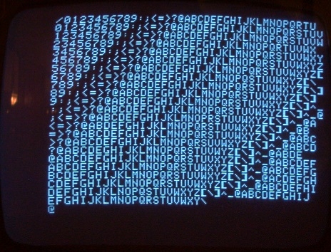
This is another one of Uncle Bernie's technical notes on how to diagnose and fix yet another Apple-1 malady: missing characters. This disease is best reveiled when running the diagnostics page that comes with the A1,A2 PROMs of my famous IC kits, but you can also type in the small character stream output example program from the Apple-1 manual. If your Apple-1 has this disease, the screen output looks like this:
The missing characters should be obvious. Most go missing on the last character position in a text line, but actually, they may go missing anywhere, this just happens more rarely, which is weird.
The reason for this is an obscure setup/hold time violation on the CB1 input of the 6520 PIA.
I use the word "obscure" because so far I did not find any clue in a 6520 datasheet from any manufacturer that CB1 does actually has any setup/hold time criteria. So take this as a tentative guess based on my experience as an IC designer: there ain't no input to any state machine having a clock which will allow you to violate the setup or hold times of any flipflop within that state machine. Nobody can make this problem go away, despite the patent system has numerous examples of fools who claim to have a metastability safe flipflop. It's all a fallacy because it's impossible to avoid metastability. All you can do is to decrease the probability of this happening until you can't measure it anymore. And then you can file a patent claiming your Rube Goldberg flipflop has no metastability. If your manager is a technically incompetent moron (most are, otherwise they would not have become managers but would have stayed IC designers) you may even get a raise once the patent is granted. But the ugly truth is, the patent is not worth the paper and ink that went into it nor the usurious hourly rate of the patent attorney, whichever is less. See, you got the patent because you claimed your novel "synchronizer flipflop" is metastability free. Which it isn't. So the patent was granted based on bogus claims and it won't survive any serious litigation. This is why everybody in the industry steals the synchronizer flipflop circuits of the competition because their in-house ones don't work as advertised and still suffer from metastability. Rinse and repeat. It's a wild goose chase. And yet another fallacy: they think the competitor is smarter and has better circuits but they don't.
IMHO, the designers of the 6520 PIA (defectors from Motorola, the same guys who designed the 6800 CPU and the 6820 PIA) however did not dare to make a 1:1 copycat of the 6820 on the transistor level, so they got a worse product. I never ran into the metastability issue on any Apple-1 build based on a Motorola 6820, but had several cases with the 6520. Which does not mean the metastability problem does not exist in the 6820. Metastability is inevitable, once the setup and hold times are violated, remember. But I have a hunch the 6820 transistor level circuit may be sufficiently different from the 6520 to have the problem at some other relationship of the two signals in question. So Woz may never have seen missing characters in his originals. Who knows. All this is only my conjecture based on the scarce evidence at hand.
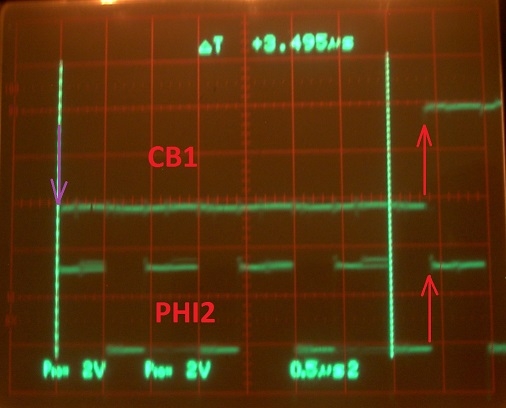
With the 6520, I ran some lab experiments to get to the root of it, and I saw that whenever the rising edge of the CB1 signal on the 6520 PIA pin #18 comes near the positive edge of the PHI2 signal on pin #25 of the PIA, characters start to go missing now and then. The signals always jitter around a bit due to the ringing of the Apple-1 supply lines and the "ground" which is bouncy and dubious, too, so sometimes the rising edge of the CB1 hits the "magic" point in time where the internal flipflop(s) go mad (metastability !) and the circuitry does not work properly,so a character gets swallowed. Here is a screenshot from an oscilloscope showing this situation:
For the photo, I have positioned the cursors to the points where the 74123 output pulse would be 3.5us wide (as specified by Woz) and you can see this would be at the falling edge of the PHI2 signal (or "E" on the 6820). The problem manifests itself on the 6520 if the falling edge moves to the rising edge of PHI2. Alas, with the common tolerances of the 74123, the 1nF ceramic capacitor, and the "10K" carbon composition resistor, there is absolutely no guarantee that the timing of a particular Apple-1 turns out to be just right (3.5us). I do my best to mitigate this problem by providing hand selected resistors for the particular 74123 in question (which never are the 10 kOhms of the original schematic) and I also hand select the 1nF capacitors, but this only helps so much, as all the components may drift when soldered in. So far I had one case of this dropped character effect happening to one of "my" builders using these selected parts. So we need an additional remedy for the disease other than just relying on hand selected timing components, just in case.
The remedy is simple: increase or decrease the timing resistor near the 74123 (the "10K" place) a little bit, maybe 5% or so, or add a few 10's of pF of capacitance to the 1nF timing capacitor, which should be enough to move the rising edge away from the "magic" spot where metastability may occur. The timing requirements of this signal as such are not too strict unless it gets to that "magic" spot. To decrease the timing resistor, you may put a 200...240 kOhm resistor in parallel to it, which you can do on the solder side of the PCB. And the problem should be gone once and for all !
Comments invited !


I've had the time recently to do a few more experiments with this troublesome oneshot.
It turned out that the pulse width timing (nominal value 3.5us as seen in the schematic) is very, very uncritical as to the range in which the Apple-1 output character handshake works. I tried pulse widths from 2.6us to 5.0us and it always worked fine, EXCEPT if the delay is at the "sour spots" where the missing characters appear: 2.9us, 3.9us, 4.9us, ...
These "sour spots", of course, are the same metastability problem pointed out in the first post of this thread. If the rising edge at the CB1 input of the 6520 PIA gets close to the rising edge of its PHI2 input, then the problem may occur. Note that CB1 is driven by the /Q output of the oneshot. If you probe the Q output, the falling edge is the critical one.
THE DANGERS / PITFALLS FROM THIS EFFECT
Because of the wide timing margins over which this handshake circuit works, Apple-1 builders (which include me) may be tempted to use timing components on the 74123 which have high tolerances and possibly are less stable than more expensive components. As far as I can tell from photos of originals, Apple (meaning the fledgling Apple Computer Company in the garage) apparently had the same attitude towards these two humble parts: a ".001" cheap and instable ceramic disc capacitor and a likewise cheap and instable "10K" carbon composition resistor. Both kinds of components are known to drift during soldering and are never the same again afterwards. And they have terrible temperature coefficients, too. For the other oneshot in the 74123 which controls the more critical DRAM timing, they used a much better (and more expensive) 47 pF Mica capacitor (the most stable and tightly tolerated, low TC capacitor available 50 years ago), and then ruined this by adding another one of these crappy carbon composition resistors (the "27K" one which never produces the correct timing with all 74123 from various manufacturers and ages I have investigated), at least this is the evidence I see in the photos of the originals. So the timing for the DRAM in the Apple-1 originals must have been all over the place despite of the high quality Mica capacitor. Maybe this contributed to the notoriety of the Apple-1, who knows. I would be curious if they (Apple) ever did use better resistors for the DRAM timing oneshot. There were 1% tolerated resistors around even back in the day, which were more stable, and did not drift much due to soldering. And far, far more expensive, of course. Or did they measure the timing on each Apple-1 and replace the "27k" resistors which had drifted too much ? ... Not exactly a good way to "mass produce" any computer. Leave this fiddling and hand tuning of components to the instrument makers like HP and Tektronix ... they got paid for that type of "magic". At least back in the day. Nowadays everything is digitally calibrated in software.
DRIFT OF CARBON COMPOSITION RESISTORS
I did some experiments with carbon composition resistors (as I provide them with my kits) and the better ones (the RCR military types) drifted only about 1...2% due to soldering, typically upwards in resistance. With the "civilian" or non-RCR types I have seen drifts of 7% and more, which exceed the 5% tolerance band (and adds to it).
Now do the math. If a given set of resistor and capacitor hits exactly 3.5us when tested, how much can they drift until they reach the critical zone at 3.9us ?
The answer is: +11.4%
And this may happen ! I've seen this magnitude of drifts for certain R C combinations. So I started to supply Mica capacitors for the ".001" place which don't drift in any significant way. But because I could not find any sufficiently stable carbon composition resistors in the 11 kOhm range needed to get 3.5us out of a 1 nF capacitor, and because these 1 nF Micas are "the next size up" which makes them unwieldy und ugly looking in the Apple-1, I opted for 750pF Micas and 15 kOhm carbon composition resistors. Just in case the latter drifts too badly, I also supply a metal film resistor in my kits as a spare.
I think this is another piece in the puzzle on how to make Apple-1 kits that work. It's not that I want to spill my "secret sauce" all over the place on this fine website, but at some point I will stop making these kits and so I want to preserve some of the know-how for posterity.
Comments invited !