Looking at the II clock circuit because I'm not seeing a clock on a 79 II motherboard. At first I thought it was a problem with the crystal because I was only seeing a high output from Q2.
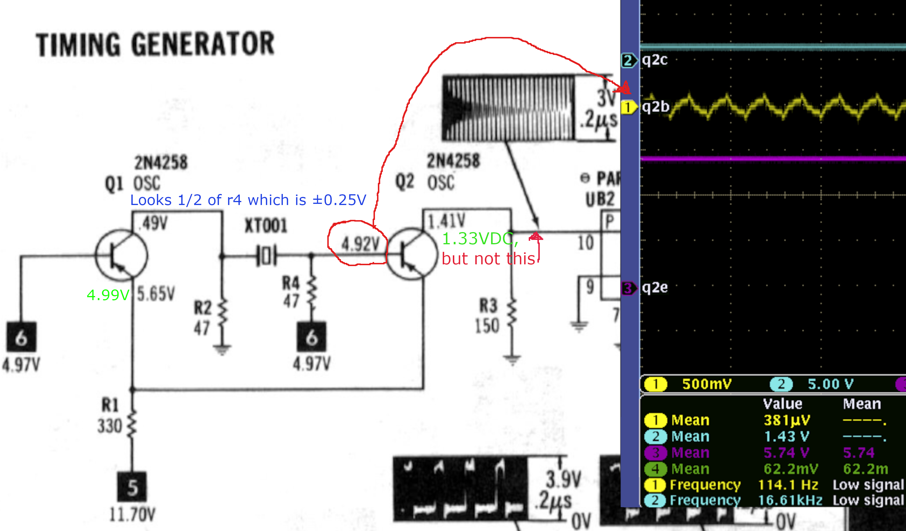
Looking at the SAMS Compufact Apple II / IIPlus I see the following information on the timing circuit, so I took some measurements:
It now looks like Q2 may be bad, and I can pull that and test, but a quick search online shows these parts are long gone. Is there a suggested replacement? I grabbed a datasheet from an archive site so I have the specs, but don't want to search out my own if there's already a good replacment know.
Looks to be a fairly simple part of the cirucuit, but I may have missed something.... is there something else I should check before messing with Q2?
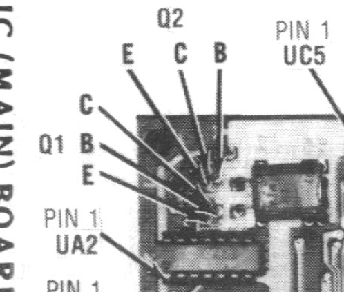
I am not a fan of the way the author calls out the transistor pins on page 18 (board picture) , is right, but hard to clearly see and I was wondering why there are two of the same parts on this board. Even at 300% this was not clear to these old eyes lol:
They are not gone, you can still buy them: https://www.findchips.com/search/2N4258
You should not put the oscilloscope probe right at the crystal. Put it where the SAMS book suggests instead.
... a lot has been written here on Applefritter about the challenges with them. It also could be a damaged crystal ... this type of oscillator tends to overload the crystal (most simple crystal oscillator circuits do that) and then the abused crystal gets damaged and refuses to work.
Finding the right (series mode) crystal for the Apple II is difficult. You can use a parallel mode crystal with a small (i.e. 47 pF) trimmer capacitor in series but if that thing starts up is yet another question. Some crystals do, others don't.
For more information, see the various threads here on Applefritter on the topic.
- Uncle Bernie
Thanks, I was probing the transistors but understand there's nothing between.
The clock divider outputs were as expected when there is no pulse train. You got me wondering how to check the voltage references they included.
Given what I'm seeing I'm thinking the transistor(s) are the first thing to try, but only because I don't see anything else it could be.
Voltages from the supply measured at the slot connectors are : 5.15, 12.7, -5.3, -12.5 all within 5%.
This board also came with a bodge wire from UB1p16 to UB2p14 wihch is power but I can't see anything that would indicate any trace problems, they both get power from different sides of the board. The topside trace (B1 74175 FF p16 ) looks good, as does the bottom side (B2 7486 EOR p14) also looks good. Now I'm second guessing if I should just pull those chips and verify they are good as that's easy enough to do.
I will do so, but do you have suggestions on what to search for that will get me there? I had searched for the transistor part number, and to my surprise there was nothing. Searches for other clock oscillator stuffs mostly returned things for Mega 1 and/or overclocking. I didn't find anything helpful related to the II.
Jeff d, does your image indicate no output signal on the collector of Q2? e.g "but not this" No signal here indicates an issue with Q1, Q2 or the crystal if all transistor bias voltages are good.
Yes, the "not this" is hte collector signal. I was trying to use the red arrow to point to the line the graph is pointing to... guess that could have been done better. The Q2C in the scope image is what I see, ie a steady 1.43V with no oscillation. The green voltage values are my readings which belive are "good".
In post #5, 'jeff d' wrote:
" I will do so, but do you have suggestions on what to search for that will get me there? I had searched for the transistor part number, and to my surprise there was nothing. "
Uncle Bernie says:
There have been numerous threads and posts about Apple-1 and Apple II crystal oscillators and their problems. But I also do have issues finding them again. Here is one thread on the Apple-1 crystal oscillator which is as botched as the oscillator of the Apple II:
https://www.applefritter.com/content/wanted-apple-1-owners-frequency-counter
The fundamental problems in that thread are discussed and apply the same way to the Apple II: if you get the "wrong" crystal and if it starts oscillating, you still may have the wrong frequency (not the 14.3181818 MHz stamped on the crystal) and so your colors will be gone.
The trimmer fixes that as you can 'pull' the crystal to the target frequency.
Once you have that trimmer (and a parallel mode crystal, which is easier to obtain) you can also use a lot more transistor types. I think most small signal PNP transistors could be used sucessfully, but I did not try that. One problem with the original series resonant oscillator circuit is that ideally there should be no reactances in the loop, which means the transistors must have very small parasitic capacitances, or, specific ones which fit to the specific crystal. Otherwise the oscillator may not start or refuse to work on the proper frequency. The oscillation criteria for the phase and gain around the loop are not well understood by most hobbyists, and some "professionals", too. There also are many misconceptions as to the differences between series mode and parallel mode crystals. See my post #16 in the above thread for more insight.
The bottom line is this: don't try to find a "series resonant" 14.3181818MHz crystal for this oscillator, because they are hard to find and most likely won't work in that circuit unless by sheer luck they are very close in certain parameters (not found in most crystal datasheets) to the ones Apple did use. Instead, go for a "parallel mode" crystal (which are easy to get) and add the trimmer. But don't expect that everything works instantly ... you might need to tweak the circuit a bit, i.e. adding small load capacitors (10...33pF) to ground.
There is a reason why the industry nowadays avoids to design their own crystal oscillators, and uses the ready made "canned" ones in DIL-14, DIL-8 or various forms of SMDs. Proper design of crystal oscillators is a lost art ... and even most books written by "authorities" in the field have misleading recipes or fallacies. For instance, in one such book, their best oscillator (crystal in the emitter to ground path of the sole NPN) sports a large parallel inductor there ... hmmm. The author claims that it won't work without that inductor but also states the reason why is not understood. (Ouch).
I laughed and replaced that nasty inductor with something else ... and this book is supposed to be one of the best available on the subject.
I could tell you stories ... designers desperately trying to simulate a crystal oscillator with SPICE ... never works, always lies ... oscillators for wristwatches which stop oscillating when the watch gets a small g-shock, and only restart seconds later. (CASIO exploited that common behaviour of some competitor's watches to turn that into a brand name for their watches which had a better oscillator circuit). Never underestimate the pitfalls lurking in crystal oscillators and never build the lousy circuits shown in all TTL and CMOS databooks and cookbooks. All of them are bad despite they pretend to work ... until they kill the crystal by overloading it.
- Uncle Bernie
You can still use the oscilloscope to measure voltages, just ignore the oscillogram. In the SAMS books when they put voltages like that, they are to be measured with a digital meter set to DC relative to the common ground.
To eliminate the possibility of anything other than the generator, you can simply remove the 74S86 chip in position B2 from its socket and then take a look at the oscillogram on pin 10 of the empty socket. If you still get nothing, then the problem is definitely in one of the elements making up the generator.
Thanks Uncle Bernie. I am one that understands what I don't know and once I saw clock high I though oh nooooo not the clock...
I had a talk with the board's current (not orignial) owner tonigh and had said many of the same things, including this is generally done with a single part these day. Your description of trying to work in a differetn crystal sounds full of problesm or a lots of effoet to get dialed in. Sounds like a fun challenge, or hell!
I think a good plan is to work back to this, and hope it's something else in that path. I'll start with the ICs and work back to the oscillator.Without an obvious reason for the bodge wire, I can't help but wonder if the original owner was attempting to fix something with either the XOR and FF, so maybe this is related... ? I don't know. Just power bu without obvious trace damage so curious to it seems strange.
Thanks for the suggestions, that is similar to what I was planning to do. I was going to pull B1 and B2 and test them. The reason for B1 is because of the wire.
I had been wondering how to isolate the generator from other circuit stuff, and hadn't yet got that figured out. You suggestion to deadend the singal at the XOR will do the trick, thanks!
Couple of updates, tried CVT's suggestion of removing the EOR and found voltage on B2p10 but it was steady at roughly the same voltage as in the earlier picture. Also noticed is pin8 (output) was sitting at 1.5V which I didn't trace through the schematic, but expect that's fine (unless someone knows otherwise). I may look later, but this point I I'll let that slide.
I removed the bodge and was done for a good reason, B2's power is lost without it. I wonder what's going on behind that socket after looking at the pad and pin can't see any problems. The original work was well done, pro work. I don't think Apple would have done that, but who knows maybe it was a production rework... anything is possible in production.
I reflowed the transistor joints and took a look at the X1's joints.... someone else had touched these. They weren't horrible, but also not well done and better now.
No change but during a discussion with the owner last night I did learn they were folowing the advice of others and had tried reseating chips and removing the CPU to check the board revision. Fingers crossed that all is fine, but I should check things I didn't think to check before noticing no clock on the CPU. I think he said he may have inserted the CPU wrong, but I now wonder if that would have been discoverd after applying power or what. I'll be tracking down transistors today....
With the 74S86 removed, this is what you should have seen on pin 10 if the generator was working:
Generator.png
That is definately not what I'm seeing.
I was wondering about rather than harvesting parts from a II, this looks like the same core parts as is found in the //e but I don't see any specifics on the Y1 in the //e other than it's frequency. Could a replacement for the oscillator and transistors come from a donor //e?
Two other notes on the hunt for replacement transistors... the PN4258 is easy to find today, but not the N and finding having to double check what's available is not really the PN. Also those line item and order minimums along with shipping >$20 for two tiny parts is >$40 for two transistors which I find crazy! I could have an emu running on a pi for about the same! LOL
Yes, you can take the crystal and transistors from a IIe, if you have one lying around for parts.
Thanks, the replacement search is feeling more hopeful!
Bring out yer dead II's!
All Bulgarian Apple2 clones (except Pravetz 8C which have an oscillator) use 2N3906 in the very same ciruit instead of 2N4258.
Also there are some 2N4258 on eBay: https://www.ebay.com/itm/404088565243
In post #16, 'jeff d' wrote:
" Bring out yer dead II's ! "
Uncle Bernie complains:
IMHO it's a sin to cannibalize another Apple II just for the oscillator components.
It would be better if somebody made a small kit based on a 'parallel mode' crystal, a trimmer, and the two transistors to allow replacing the original oscillator circuit. Such a simple solution of course would also overload the crystal, so it will die sooner or later (I see this as the primary cause of all the oscillator trouble with the Apple II) but these 'parallel mode' crystals for 14.3181818 MHz are easy to find and cheap to replace.
Anyone who tries to preserve / repair the 'serial mode' crystal oscillator will have huge difficulty sourcing the right components. Even back in the day, Taiwanese clone manufacturers faced the same crystal oscillator woes and so their cloned motherboards often had added pads and traces on the PCB to put in extra components around the basic oscillator circuit they copied 1:1 from Apple. These 'options' would allow them to make the oscillator work even with 'parallel mode' crystals and they could then tweak the frequency to the required accuracy (otherwise, no colors !).
It eludes me why Apple II users facing a failed oscillator always choose to go the hard way full of pain, suffering, and additional costs. Maybe the choice of that problematic 'serial mode' oscillator by Apple was done intentionally to make cloning of the Apple II more difficult ... it's quite hopeless to produce such clones unless ordering the right 'serial mode' crystals from the crystal manufacturer, which must be tailored for that specific oscillator. Otherwise the oscillator won't start, or the frequency would be off target. This, BTW, is the reason why 'parallel mode' crystals are preferred and dominate the marketplace. They can be 'tweaked' to target frequency and oscillators based on them start better and run more robustly than series mode oscillators (which theoretically are more accurate and more stable). The reason is the different region on the phase over frequency chart of the crystal on which these oscillators operate. But explaining these details to hobbyists is hopeless. It involves higher math far beyond what typical hobbyists do master (in terms of math). Remember the old adage that half a year experimental work in the lab can replace half an hour of invoking evil, higher math, on a piece of paper. Magic spells come to mind ... the modern DIE way (or is it called DEI ?) is to work experimentally - no evil math - even for pedestrian bridges or aircraft hangars which then may collapse during construction or shortly after the opening ceremony. The collapsing pedestrian bridge killed a few pedestrians who happened to use it at the time of its collapse - oh the great virtues of DIE and 'diverse' design and construction teams ! No need for real structional engineers anymore ! No need for evil math ! No need for the ability to read and write ! It's called 'progress' as in 'progressive' !
- Uncle Bernie
Alright back at this... I've tried a few thing and while adding the pico var-cap was an option I regressed back to just a used donor crystal and using a very cheap frequency counter which was very close 7.000.001 on a 7MHz signal generator which should be fairly accurate I decided this cheap thing was "close enough" for what I'm needed. It's a cheap no-name amazon sourced PLJ-8LED and I have spent almost no time figuring out how to use it other thna verify the signal generator output to measured frequency accuracy which I think was fairly close at 7MHz (my generator cap).
I measured the II clock at B2 (the EOR 74S86) and found the clock was measured close, but not exactly right. So my question is... is this close enough? There is some front-porch and back-porch "garbage" but the CPU frequency divided down is 1.023-1.024MHz I think the long pulse was making things a little "off".
So is this close enough or do I need to try the var-cap again and get a tigher result.
IMG_6237.JPG
It seems that you've reached the point where you can evaluate the "close enough" question for yourself, given the right questions:
Thanks Scott, AFAIK there's none of the shifting of colors, but I've only got my simple test LCD currently to check. Here are some examples, where you can see what I mean about the left and right edges, that extra stuff is not there with the other II systems. At least I haven't noticed it. I am not sure the colors are "exactly right" they do appear a little washed out at least in these, the choplifter looks close but maybe off a little.
It's also an original II and the power signals look quite noisy on the board, or at least noiser than what the supply normally provides. The board may be suffering from no secondary earth ground it's just sitting on a bench and the supply/board only has the supply ground. The "bleading" "blooming" or whatever seems a bit much. I did notice the 200k pot near the video output was around 0.3 ohm so I put that back to around 27Ohm which once I figure out what the proper output level should be I can tighten that up.
IMG_6054.JPG
IMG_6056.JPG
IMG_6040.JPG
IMG_6041.JPG
Subject (2).png
Now that I'm looking at it, maybe choplifter looks better toward the right (at the ground) but the red at the right edge looks odd, but so does the other stuff happing outside the frame...
Is that scope capture your 74s86 pin10 input? Now that I've got a clock signal I'm floored if that's how your generator output looks! that's beautiful and what I'm seeing is not at all that clean! I'm also on a non-RFI rev 3 II so that could be part of the problem. =)
Yes, it is. I used my oscilloscope to capture it at the time of posting.
It's not a surprise that the modern crystals don't quite produce the desired frequency so I'm diging into the picofarad trim caps and haven't yet found something that will get to the desired frequency. That said I was wondering... does it matter which side of the crystal the cap is placed? I realize we're basically playing with the RC factor of the crystal and I can go either way on if there is a difference depending on which leg is used. FWIW I'm just trying to get something to match the PLJ-8 counter which reads 14.318153 on a working //e. The reading on the II with the jameco crystal was nowhere close at roughly 7kHz low around 14.311MHz. I only found 3 at jameco (3-13, 2.5-5, 9-50 puf) and with any of those I couldn't get the frequncy dialed in. One couldn't get above 14.317, another couldn't get below 14.324 and I don't recall what happened with the 3rd. They unfortnuately all came in a single bag and I didn't have a way to figure out which was each. So I'll grab a few from mouser which will do a better job of labeling each. =)
In my testing had the cap on the leg closer to the board edge than A2 which I beliece is tied to R4 rather than R2. Does that matter? I cold enen see needing to balance both but expect that may be a bit much too. I still know ver little about this corner of the circuit!!
It doesn't. I usually use round-hole IC socket pins to make a little 2-pin socket for the crystal + trim capacitor. Once I set up the trim cap to produce color, I can plug it the other way and it still works.
I just recently finished converting a Pravetz 8A (Apple IIe clone) to NTSC-50, which I sent to a friend in the US. The idea is that he will change the IOU with one from an American Apple IIe and he will have regular NTSC. I bought the parallel circuit crystal from an electronics store in Bulgaria: https://vikiwat.com/en/quartz-resonator-metal-14-3181-mhz.html
Pravetz8A.JPG
Pravetz8AGame.JPG
Pravetz8ATotalReplay.JPG
Thanks!! I have been concerned I am getting to the point where I could be stressing out those crystal pads. I had been thinking about doing something similar with the connectors found for thinkgs like the thin lead bulbs (keyboard power light), but didn't know what a pin socket like that would be called.... I guess I don't need to know and can just pull some from a machined socket with some heat!!! Great idea!!
No need to use heat - I just break up the plastic with my wire-cutters.
If the crystal came from an Apple IIe as you mentioned above, there is no need to add a trim capacitor, because it's already the right crystal (designed for a serial circuit).
Btw is this Apple II+ motherboard switched to 60 Hz? If it's a European version Apple II+ still at 50 Hz, you are producing NTSC-50. You might want to switch it to 60 Hz, because most LCD displays and CRT TVs in Europe have trouble with NTSC-50. It is not really an official standard.
Also when adjusting the crystal frequency using the trimmer cap, you don't really need a frequency counter. All you have to do is display a color graphic and adjust it until you like what you see. As you are adjusting the computer will almost always crash as soon as you touch the trimmer, but the graphic usually stays on the screen.
Thanks for the info, I did something which I thoguht wsa kinda neat with the machined sockets, I basically took a row and removed the 2 and 4th pins then cut at pin 4 and left 2 open. The spacing was right for that to be slid into the crystal pins so it's got a little more support than two naked pins and looks pretty nice! There are more updates on the tuning, and I'll say this for now I should have thought about the math before this but need to understand you can only slow down the clock with adding capacitance. If you want to speed it up the resistors would need to change. I had been wondering about if I should be considering the resistors up to 68 (from 47) rahter than the cap but I didn't. Instead I found I needed much more capacitance than expected and this was discovered while stacking ceramics. Only after adding in 10nF did I see the frequency drop down to 14.317 when it was closer to 14.320 without any added capacitance. I think I've finally found the value needed is 220pf which puts me within 10Hz of values measured on other IIs. I'm doing a heating test right now, and if stable I'll then check the video. I'm excited, and hoping I'm able to wrap this up!
FWIW, this is not a crystal from another II it's one someone gave the owner when supplying ROMs, and it was running at 14.322 in it's bare as seen on pin10 of the B2 (7486).
Ah I forgot to mention why the "speeding up" was something I was trying to figure out rather than just an exercise in theory.... the two crystals I got from Jameco which are 14.31818M were measuring at 14.311M so if I was to get those to increase their frequency I would have had to reduce the resistance, because adding capacitance will only slow down the frequency. So, I'm saying to avoid the crystals currently available at Jameco, if interested they're unique as they have a 3rd lead off the top of the can that I expect should go to ground and it doesn't make any difference if it's grounded or not, still runs at the same slow frequency.
Adding a capacitor in series with the crystal increases the frequency, since it decreases the overall capacitance. I don't understand why you don't do just that. In all the machines I converted to NTSC using "parallel" crystals, the trimmer capacitor is always set between 20 and 30 pF.
Also you don't need to be exactly at 14.31818 MHz. As long as you are within a certain range, an NTSC TV will display color.
I did this investigation for another topic, so here are the frequency ranges in which the 4 NTSC displays that I own fully retain color and display it correctly:
46" LCD Sony Bravia KDL-46XBR4: ....... 14.314473 - 14.321391 MHz
14" CRT Sony Trinitron KV-14T1R: ........ 14.316686 - 14.319890 MHz
14" CRT JVC C-F14EE: ........................ 14.314677 - 14.320577 MHz
4" LCD car monitor from AliExpress: .... 14.312184 - 14.325282 MHz
The method that I used to determine the range can be seen in this video.
Thanks. I guess what has not been clear is I have been doing exactly what you've been describing with adding the series capacitance. But in doing so I found the capacitance was no where near the very low 10-50of that wasn't doing enough. With the trimmer cap I could see that I'm looking at this backwards... that's toally possible! I can see the error in that after refelecting on what I'm seeing. But I've also wired in ceramic caps and seen the frequency drop as the capactiance increases. So that's a little puzzling.
I've got the base generator back at 14.317.7xx which is close but I've lost color and v-sync so seomthing broke while trying to get it back down around 14.318. Now I need to look at the rest of the signal path, but expect one of the tranistors near the 200Ohm output level pot (likely Q6) may have failed so I'll need to track down a replacement for test. Given I don't have color and sync I think Q6 would be a good place to investigate.
Also keep in mind that even though adding a trimmer capacitor in series with the crystal increases the frequency, increasing the capacitance of that trimmer decreases it.
For example here are the frequencies on Pin 10 with the 74S86 chip in position B2 removed and a 14.31818 MHz crystal:
No capacitor, just the crystal: 14.3082 MHz
A 11pF capacitor in series with the crystal: 14.3196 MHz
A 22pF capacitor in series with the crystal: 14.3151 MHz
A 44pF capacitor in series with the crystal: 14.3120 MHz
Wait, what? That now sounds like you're now saying what I was saying earlier where increasing the capacitance lowers ther frequency... that's why I said it appears all that can done is to lower. I do not see it increasing.
I was just about to transcribe my numbers to share when I saw your update which mirrors what I see, higher capacitances slow down the frequncy which would meake seense from an RC timing perspective.
No doubt, this is a little confusing....
Are you saying the trimmer is dual-modal? Meaning that for a range the frequency will increase but outside that ragne (higher capacitance) the behavior is reversed? This would explain why I was confused by what I was seeing with the trim cap and after your previous message I decided I was just looking at it from the wrong perspective, but now I'm more confused. LOL Adding to the confusion is that I don't have a meter sensitive enough to measure the trimmer capacitances so I'm flying blind and don't know if I'm staring and min/middle/max and if the rotation is increasing or decreasing. All I can see is the frequency changes. And like you I can crash the system if the 7486 is installed as I change the capacitance. But I need to figure out the color and sync inssue before I can follow up.
I also observed the frequency out from the 86 (pin8) is also slower than the input from the generator (pin 10) it's not much but is slower and this is the correct 74S86, not the slower LS or other series.
You need to look the equivalent circuit of a crystal in order to understand what is happening. When you add a trimmer capacitor in series with a crystal, the overall capacitance of the system "trimmer capacitor + crystal" drops, so the frequency increases. As you then increase the capacitance of the trimmer capacitor, the overall capacitance of the system also increases, so the frequency decreases.
You can see why this happens if you simply imagine a 2pF capacitor. Its overall capacitance is 2pF. If you then connect another 2pF capacitor in series to it, the overall capacitance drops to 1pF. If you then increase the capacitance of one of them from 2pF to 3pF, the overall capacitance increases to 1.2pF.
I think the reason you see this as "dual mode", is because you are assuming that not having the trimmer capacitor is equivalent to having a 0pF capacitor. This is not the case, because a 0pF capacitor in series with the crystal will be equivalent to cutting off one of the crystal's legs.
Well crap I was trying to add details when the edit timer expired... so here's take 2!
So the trimmer cap has a measured range of ~5pf to 80pf, but there's gotta be some error this is a cheap (but fairly reliable) Radio Shack meter which will give .000nf readings and my Fluke's won't go that low.
So at ~5pf 14.324M
at 80pf : 14.320M (only a 4K drop over 75pf)
no trim cap, 14.3177M
So clearly the small capacitance add provides a boost, and increasing capacitance lowers that. I believe to get to a "close" value with standard ceramics I had laying around I didn't get to the 14.318 until 330uF was added to the crystal.
What? No trim cap: 14.3177 MHz???
This means you have a serial circuit crystal and you don't need a trim capacitor. Does the marking on the crystal contain an S? Every single NTSC display that I own would strait up work in color with that frequency! Is your display not showing color just with the crystal alone??
This recipe with the trim capacitor in series is for parallel circuit crystals, where the frequency just with the crystal is similar to mine, in the vicinity of 14.3082 MHz, which is way bellow the range of any NTSC display.
Also can you take a picture of this part of the motherboard? I want to see if it's set up for 50 or 60 Hz:
60Hz.jpg
Thanks and yes, no trim was "close" with that one crysal, but with the two purchased from Jameco the frequncy was 14.311M which givne it's also serial was not acceptable. I was not clear that the trim was only needed for parallel configurations. Serial trim does affect frequncy still.
The 14.317 crystal is a tkd 14.31818 and does not have a S, the ones form jameco are txc 14.31818 with the grounding pin coming off the top.
IMG_6320.jpg
The board is configured just like yours, but not a manual solder bridge, NTSC
IMG_6318.jpg
I'm currently thinking the color problem is a result of Q6 and a I got a replacment on the way. As you can see from the pictures earlier of the games, there's some "odd" stuff with the colors and what's visible in the blanking periods the front and back porch stuff is not visible on that monitor with other systems (including other rev 3 board, II+, and several //es). Also think it's worth repeating when received the 200Ohm pot was practically at 0Ohm so the output signal may have been too high, I didn't discover that until much later and expcet that may need to be higher resistnace for some attenuation on the output. I didn't yet look into what the correct output level should be, but did dial back to 27Ohm which was seen on my other II as just a random starting value. I'll figure out the correct level before the new trasistor arrives.
Since you have a frequency counter, to see if a crystal is designed for serial or parallel circuits, all you gotta do is see how much the frequency of the crystal by itself differs from the target frequency of 14.31818 MHz. If it's less than 1 kHz as is the case with the 14.3177 MHz one, it's a "serial" crystal and since under 1 kHz is within the acceptable range of every single NTSC display out there, you don't need to do anything.
If however the difference is 14.311 - 14.31818 = 7.18 kHz under, it's definitely a "parallel" crystal and you need the trim capacitor in series.
Your motherboard is already set to 60 Hz from the factory, so the composite video signal that comes out is regular NTSC. You might want to adjust the "COLOR TRIM" located on the right edge of the motherboard, until the colors match those you see in AppleWin, because right now they don't. Also try another NTSC display. The artifacts that you see on the right side might not be related to the color carrier frequency at all. It could be simply that particular display not liking the signal.
Thanks for that feedback, all noted and as stated at the start... this oscillator and everything about it (aside from the XOR buffer) are new to me! So, all very helpful information. Thanks!
2021_0520_192330_003.JPG
I just checked tracking and with any luck it will be here later today (provided tropical strom Debbie doesn't rain on my parade).
Alright so that transistor was not the 3904 but the MPSA13 (darlington transistor) and that would have help to correctly ID frist. There's something to be said about component IDs silkscreened on the board! That was a fun (sarcastic) detour.
I thought I found a cracked 74747 from A11 (maybe?) and after getting that replaced fired it up and had sync back. But restoring the original 7474 and I still had sync, I've also had the 16K memory write/verify sweep running for a while so things are "stable" but I still don't have color back. I have verified B12p12 looks good, and the 3904 near the color trim is good and color trim doesn't seem to have any effect. I confirmed the ouput of B2 is close 14.318200 so very close. I've verified 14M somewhere else in the circuit and found it's very close to where it should be so at this point I think it's something other than timing.... but we'll only know when I can find what's killing color (and I'm in graphics mode so it's not the color killer. I think I'm seeing color bursts, but need to verify those are correct. I have no checked any of the 555 timers and since those are easy to swap I may just do that for my sanity.
Well, and I knew this but was kinda ignoring it, just because a logic part passes a "tester" test it doesn't mean it's really "good" it just means it can pass some basics tests, it's better to think of them as "bad verfication" tools meaning when they fail you know they're bad otherwise it may be good or bad.
Looking at the ouput from B13p1 we see this:
tek00072.png
This looks perfect, color burst 14 pulses at 4V!
But if we look where this signal goes... B12p1 we see this (please note the 7411 did pass tests!!):
tek00073.png
Well now, that looks odd!
Checking B12p2 we get something equally odd:
tek00074.png
Swapping out B12 gets things back to where the should be on B12p1:
tek00080.png
And color has returned! That was a PITA but now I can move on to the color trim adjustments.
This is precisely why I don't use chip testers, frequency counters or oscillographs when I fix or modify Apple II machines. I just swap chips and elements and look at the result on the screen and I am usually done in minutes. Now that I think about it, the only times I was using my oscillograph on an Apple II was always just to show how a particular signal should look to someone else! :)
Yeah, I've always had the questions in my mind about testers, including if I can change the execution speed, tweek the order of singal changes, etc. There's a lot to consider and just supplying inputs and checking outputs deiven by a truth table does leave room for error. That said I'm a fan of system verilog and do know there are better ways to test parts. I made something one weekend to test 7400 parts on an Uno and I was able to account for some of those things I felt were important it did a good enough job that I was able to find several bad "good" chips.
That said, I think the video output is much nicer, but there's still this "column" artifact I'm seeing in text which I think may come from the char generator at A5 the 5318 or whatever it's number is. I've probed pins and even pins that aren't connected are showing signals that look like ouputs but only a couple hundred milivolts. The noise on 5V line is also insane, like 1.5Vpp which may even be at a high frequency so I may look into the clock generator ICs and swap out anything that comes in contact with whatver frequncy that noise is at (I'm guessing 14 or 7M)
IMG_6349.JPG
IMG_6344.JPG
IMG_6345.JPG
This is 5V signal pretty much throughout the board but input is not like this:
5v.PNG
And this was just probing B11p8, and it's using the board ground which isn't tied to earth ground so I know there's factors outside just the board but the board has some noise problem I need to find and addresss:
noise2.PNG
From my point of view that's a ridiculously high price these days for the most standard crystal resonator in the world. It is available on every scrapped PC motherboard too. I got full box of original Bulgarian crystals from the very same era that Pravetz computers belong to and were implemented in them, but I never needed such crystals since all the time these resonators are left from disposable no longer used devices. This box reminds me of ZEPE (later InterQuartz) factory for crystals that was one of hundreds industry plants built during socialist years and and later destroyed/privatized (along with the education system) in the early nineties when Western world invaded our countries peacefully. My father in the late eighties was deputy CEO of that factory and leading engineer. When I was 16 as part of then widespread practice for students to work for several weeks per year in factories I worked one summer month at a machine in ZEPE factory plant where the short series custom (non-standard) resonators frequency was adjusted. That was a noisy big vacuum stand and the specific job was rather tiresome.
IMG_3969.JPG
Now this particular situation I have seen on multiple occasions. It happens when the colorburst is missing (or not fully suppressed), but the display is still trying to interpolate it from the signal itself. One mitigation that often works is to decrease the signal level from the potentiometer located at the top right corner of the motherboard.
From which "signal itself"? How is such "interpolation" done?
Thanks the 200ohm pot has been adjusted and dialing down the resistance does change the output signal (duh) and brightness (best term I can use to describe how lowering washes out the image). As you konw it's a balancing act between the level and then color trim to get things dialed in.
I'm currenlty looking at the signals on the chips in the A2-A3 area and one which should have nice pulse train has this sin shaped interruption in the middle of the normal pulses. I'm looking into why but found I don't have any spare 74LS00 chips (that was a big surprise to me!) .
strange dip in B2p3.PNG
The zoom aliasing give a neat view of what's happening:
strange dip in B2p3 (3).PNG
B2p11 which is used in generating the video data does some interesting things which I haven't looked at closely, the is a pattern, but I haven't figured out what it is yet. Will investigate this further. I'm questioning all the chips involved in the video ouput so there's a few things I need to study and understand.
b2p11 (1).PNG
b2p11 (2).PNG
b2p11 (3).PNG
When it's a color image with a missing colorburst (just color bars for example) it would be from the sine wave you see on each bar itself. When it's a monochrome image with the colorbusrt not fully suppressed (as is exactly the case in text mode of the Applle II+), it's from the not fully suppressed colorburst. This is why lowering the signal level helps in the latter case, as I suggested already. When you decrease the level of the entire video signal, the amplitude of the suppressed colorburst gets even smaller and at some point the display no longer picks it up.
I have seen this happen on Trinitron TVs. Lowering the signal level fixes it: https://www.applefritter.com/comment/99368#comment-99368
Pages