
I've (almost) finished assembling my Apple-1 NewtonByte Prototype. So far it passed the smoke test, but I ran into an issue when the 7400 (B1) is inserted; it's displaying 4 vertical columns with random garbage even after pressing clrscr/reset. With the 7400 (B1) removed, the screen is filled with flashing "@_" as expected, and after resetting, I get a "@" prompt in the top-left corner but that's it. I am guessing it's related to having the 6800-only being populated.
Note: I followed the instruction provided by MichaelNG with the purchase of his board incl. cutting and jumping the recommened traces. I also ensured that I connected the +5V to the correct A4-6820-24 pin (photo in the intructions is wrong).
Question: Did anyone run into similar issues while building a functioning Apple-1 A Prototype? If so, what components did you used to poplate the 6800-only area to get it working and did you have to make any additional changes to the 6800-only area. (I see one more cut which is not documented).
It might be wrong, but here's what I've tried with so far in the 6800-only. It's all I had laying around and appears to match the labels on my other A1 boards
- 4x 22 uf Allen Bradley carbon resistors
- 4x MPS3704 NPN TO-92 transistors
- 2x 10⁴ 1.0 box capacitors
- 4x 1K uf Allen Bradley carbon resistors
- 4x 10³ 0.01 disc capacitors
I've successfully built two fully functioning Apple-1 (a Non-NTI and a NTI) without issues. But, the Prototype PCB is a bit different and has the 6800-only area populatd while running the 6502 CPU.
It's worth noting that I've tested the 7400 in one of my other working Apple-1's and it's fine.


Good job!
Computer A is quite seriously different from the usual replicas, the arrangement of some elements/tracks had to be "made up" using common sense due to the lack of good photos of the upper right part. I have been following this project with great interest in the FB group. I think it would be easier for you to contact the esteemed Michael Newton on this matter. I'll say for myself that Michael is one of the nicest guys from the Apple-1 crowd that I've had the honor to meet. I think he is very interested in how his board will work with the 6800 processor. Good luck!
I haven't myself tried to configure the board to 6800 processor yet, so the instruction only covers 6502 build, but below is the info which is kindly shared by Massimiliano, I hope this will help.
Other than that, for B1 7404, use 74L04 and pin 39 of 6800 should be floating and grounded through 1K 0.25W resistor.
As soon as I find time to try adapt the board to 6800 myself, I will add 6800 build into the assembly instruction.. Note, some of the jumpers/cuts shown in the instruction are not needed for 6800 configuration. Please let us know when you succeed in bringing the board up with 6800 processor. :)
By the way, for the error that you brought up, I think the instruction should show clearly pin 24 of 6820 is jumpered to +5V, though I should put 6502 inside quote marks to avoid confusion.. since pin 24 of 6820 has a connection to one of the jumpers with "6502" marking in the later boards and as shown in the schematic.
JUMPER between A4-6820-24 and +5V line
(COMPONENT SIDE)
This corresponds to the 6502 jumper at A6 in the production board.
Thank you Mike for the information and explanations.
However there must be some confusion, as I am trying to get it working as per instruction using a 6502 CPU with the 6800-only area R21 - R23 populated. (NOT using a 6800 CPU)
I will try with the recommened 2N3904 in Q1 and Q3 PNP and 2N3906 in Q2 and Q4 NPN and see if that fixes the issue.
:-D I ment to say ohm for the resistors above (not uf).
Sharing my progress, in case somebody has any suggestions or ran into similar issues while building a Apple A prototype using a 6502 CPU:
I swapped out the transistors as recommended, although as Michael also pointed out the 6800-only area is for looks only when used with a 6502 and should be completely isolated. On the back I ended up cutting all 3 traces going to the 6800-only area.
But, I still get the same results displaying the four flashing columns displaying garbage with the 7400 inserted.
With the 7400 removed, it flashes correctly with the "@_" symbols filling the screen, and I can CLRSCN and RESET. But, the computer part is not functioning without the 7400.
With the 7410 removed and 7400 inserted, I still get the four vertical flashing columns (one character width), but the characters are readable (not garbage) – A, B, @, etc.
Note: I’ve also swapped the B row ICs to a working Apple-1, and all ICs are functioning properly, so I must be missing something else. I've also checked for shorts, but found nothing.
6800components.jpeg
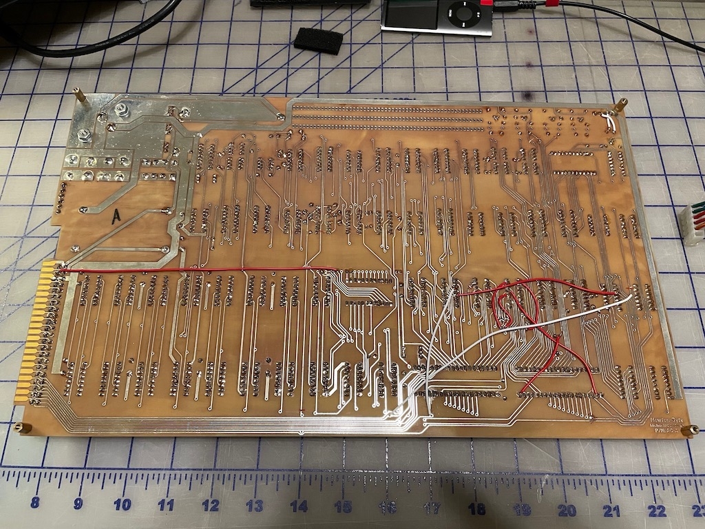
6800traces6502.jpeg
All traces leading to the R20-R23 area are now cut (front and back), and the 7404 (6800-only) socket is NOT populated since I am using a 6502. However, it made no difference. All other trace cuts and jumpers are the same as seen on the original replica board, with one additional jumper from 6820-Pin40 to Keyboard socket Pin14, as per instructions.
Hi fans,
flatsixracer finally gave up on trying to find the issue with his Apple-1 prototype clone all by himself.
Since he did the build with one of my famous IC kits, he asked me for hints and after some emails among us, his build arrived at my front door - he lives in the USA like me, so this can be done without undue postage.
Here is what had happened before (see the posts above in this thread): after building it, it did not work, despite one of my famous 100% tested and burned-in IC kits was used.
What was weird with this Apple-1 prototype build was that the terminal section seemed to work properly, as long as the 7400 at location B1 was not put in. When the 7400 was put into the socket, in an attempt to make the processor section work, the on screen display got messed up to four columns of garbled characters.
This is how I approached the problem:
Knowing that insertion of B1 would mess up the system, I bent away the output pins of the 7400 one by one, so it would not contact the socket, and then turned on the power to see if the screen display was still messed up. When I arrived at pin #11, the problem was gone. Then I probed pin #11 of the empty socket and with the other probe tip of the multimeter (on "conductivity / diode setting", it beeps when a low ohmic connection is found) I probed the various exposed traces to find the trace carrying the signal from pin #11. I found three long, horizontal, adjacent traces beween Row A and Row B. Oops. These three traces were obviously shorted. Closer inspection found a stray via that short circuited these three traces:
A1_Proto_Fault.JPG
This process took maybe five minutes, beginning with bending up the pins of the 7400. I do have some routine doing this kind of diagnostic work and so I can probably do it quicker than people less familiar with the Apple-1, but once you know the method, and the Apple-1 is on the lab bench and hooked up, anyone could do the same in maybe 10-15 minutes.
Here is another photo with the location of the fault (red circle):
A1_Proto_Fault_Location.jpg
This is between Row A and Row B, above the 6502, and below the four 74S257 which can been seen in the top half of the photo.
The remedy was to scrape away the copper foil adjacent to the via using a sharp tip of an X-acto knife, guided by a plastic ruler (do not try such work free handed, and do not use a metal ruler).
After measuring that the three traces now were disconnected from each other, I bent the 7400 pins all back, put it in the socket, and powered up the Apple-1. It worked !
Here it is running my diagnostics page which came with the PROMs in my kits (now sold out):
A1_Proto_Works.jpg
What remains as a mystery was how that stray via got there. On the bottom side it has no connections. It just looks as if when editing the layout, this via was inadvertently dropped unnoticed. In Mike "Newtons" excellent building instructions for his prototype PCBs, this stray via is not there.
After I reached out to Mike (we are working together on many things, stay tuned, he will soon start to sell the Gen2 improved ACI PCBs I developed based on his famous "Newton" ACI Gerbers) he confirmed that this stray via crept into his PCBs after the photos were taken from an earlier prototype board he had made to check his work out. For the actual production run a few small edits were necessary and this was when the via was accidentially dropped. So most of the builders of Apple-1 prototypes will have this issue. Which is easily fixed, once you know it.
Mike has made better photos for this procedure and recommends to solder this via shut from the solder side before scraping away the short circuit from the component side. Once the via is soldered shut, this prevents the tip of the X-acto knife to fall into the via hole. For me this was no problem, as I used a ruler as a guide, and I have experience with this type of repairs. You should probably go with Mike's method, filling the via with solder.
There also are some good news ! I found out that this Apple-1 prototype clone, after the stray via was fixed, works perfectly fine with no "reliability mods" whatsoever. At least it does with the INTERSIL DRAMs which I put in my later kits. On clones of "production" Apple-1 PCBs (Newton non-NTI and NTI, and open source) these DRAMs never needed additional "reliability mod" capacitors but some did need the six damping resistors, though. Other brands of DRAMs used in my earlier kits were more allergic to the Apple-1 environment and needed the full "reliability mods".
I can't say if this would apply to all Apple-1 prototype clones built on Mike's PCBs, the type of bypass capacitors being used certainly matters, and the ones used on the original prototype were the same type as later seen on the "NTI" originals, as far as can be guessed based on the photos. For the "non-NTI" aka "Byte Shop" originals they used brown ceramic disc bypass capacitors, which are known to have a worse performance . So this is circumstantial evidence that Woz fell into the same trap as many fledgling companies do: the prototype is fine, and works robustly, and then on the first production run, the big mistake is made to use some components which are different from the ones in the prototype. This may be due to running short of cash, or out-of-stock issues, but never, ever do that. Any component change must be carefully assessed in the lab for possible impacts on the product's reliability and robustness. But in the mid 1970s stringent component qualification processes and "approved component lists" were only used by the bigger outfits (such as mainframe computer manufacturers) and the rest was "Wild West" - anything goes. The microcomputer highway is littered with wreckage of failed companies for a reason, figuratively speaking. And early computer magazines of the 1970s were full of letters / comments of desperate owners of dysfunctional S-100 cards or whole computers which never quite worked. This nonchalant attitude towards product reliability and product quality in the microcomputer scene ended with the introduction of the IBM PC, which commanded a high price for the built-in quality and reliability of "Big Blue". All the microcomputer companies who could not bring their product up to snuff perished in the wake of the PC. Apple obviously survived, as the Apple II was basically sound and robust, compared to the rest of the pack. History tells us that any new industry went through the same kind of learning curve, and overall, even the ill-fated Apple-1 wasn't that bad. I think what really led them to the buyback decision was the terrible ACI.
Which I fixed, 46 years too late of course ;-)
- Uncle Bernie
A big thank you to UncleBernie for identifying the issue and to MichaelNG for your information and assistance. This discovery should benefit other NewtonByte Prototype builders also.
It was a bit like playing "Where is Waldo?" but now that UncleBernie has pointed it out. I can't believe I didn't see the fault/short while "trying" to troubleshoot the issue myself.
Where is Waldo.jpg
Bravo, well done! Uncle Bernie knows what he's doing!
I don't think we should take offense to Michael. We all make mistakes, we learn from them. The only one who doesn't make mistakes is the one who doesn't do anything.
What kind of X-acto knife is that? Like a surgical scalpel? I use some kind of manicure thing with interchangeable diamond-coated cutters. Kind of like an engraver. On one of the Apple II rev 0 versions I have to trim some of the tracks too, very handy. My wife and I have a pact: I don't touch her toys and she doesn't touch mine. But sometimes I cheat....
In the meantime, I was wondering if anyone knows if in the photo of the original Computer A prototype it's still a 1n914 diode or something else? Maybe someone knows the manufacturer or part number? I asked about it in the group on FB but unfortunately I didn't get an answer. Thanks in advance!
IMG_20230913_071829.jpg
In post #11, Macintosh_nik wrote:
"What kind of X-acto knife is that? Like a surgical scalpel ?"
"I was wondering if anyone knows if in the photo of the original Computer A prototype it's still a 1n914 diode or something else ?"
Uncle Bernie answers:
See the webpage below and scroll down halfway to "BLADES". I used the 4th from the left, but the first two also would do.
https://www.xacto.com/cutting-solutions.html
These are similar to surgical scalpels, which also come with different blades, but I think that the disposable surgical scalpels they use nowadays (the ones with a plastic grip) have a thinner blade which is not well suited for scraping work on printed circuit boards.
Note that there are many knockoffs of X-Acto knives in the world and the key feature over a normal knife is the pen type handle, which allows very exact work. You could use any knife with a sharp tip by grabbing it appropriately, but it's more tricky and requires better fine motor skills as with the pen stype handle.
As for the diode, I have no idea what that is. Color code says 0034 or 003D (black black orange yellow), none of which gets us any further.
For diode color codes, see here:
http://www.csgnetwork.com/diodecolorstable.html
As a wild guess without any further evidence, the 1N34 germanium diode was known for a very low forward voltage, and at this point in the Apple-1 circuit a low forward voltage brings better logic levels. I sold most of my kits with Schottky diodes, which have about half the forward voltage of typical 1N914 or 1N4148.
- Uncle Bernie
Thanks for the detailed answer!
It looks like the theory that it is a 1N34/1N34A diode is close to the truth. I searched eBay and found a very close variant, but with one black stripe and in a transparent case. I unfortunately did not find a more similar variant. Judging by the photo of the prototype, its length should be equal to the length of the Allen Bradley resistor. Now it is clear why on the serial board the silkscreening in these places looks a bit strange. I can assume that originally the board was designed for a longer diode (1N34/1N34A?), but later this element was replaced by a more available or cheaper one.
IMG_20230925_075422.jpg
IMG_20230925_074956.jpg
IMG_20230925_074909.jpg