Much as the title says, I finished my Apple 1 build. Overall, it worked right off the bat—no real problems, and a lot more stable than I expected. I have noticed some random memory errors when listing address contents in RAM. Stray bits in what should be empty space. But nothing significant. I guess I could try typing something into the address and checking that it reads back. But that's not my problem right now.
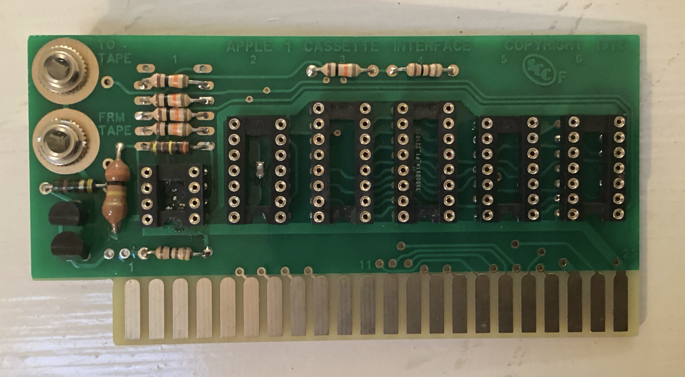
It's the ACI. The thing just isn't working and yes I know it's my fault! First, I was trying to have my cake and eat it too. I already had an ACI board based on the original design as well as the one that came in my kit. So I decided that since the kit one was an upgrade, I would build the original and use modern equivalents upgrade (2.0) board, swapping chips between the two... Not one of my better ideas, as now neiother board works.
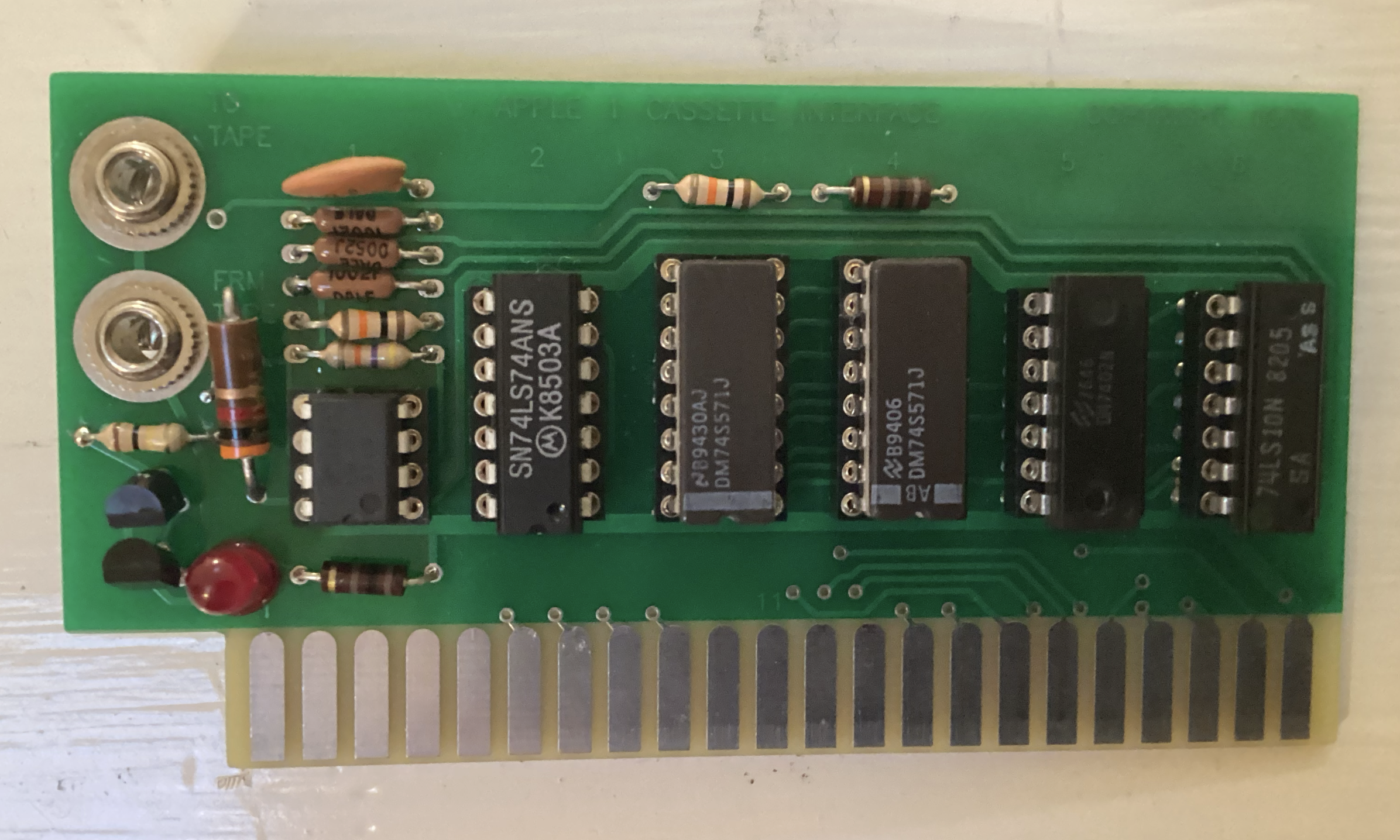
For the "Original" board, I lost a few bits in my attempts to trouble shoot. The oversized 3k resisters were all my local electronics store had. One of the 10k's seems to have disappeared on me (before the build) and the others were the wrong values for the original schematics.
I really should have focused on the Uncle Burnie board and saved the other for a side project! But this is where I am. So maybe someone could look at the monstrosities I've built and tell me the (probably many) places I went wrong. The good news is that the Apple 1 does recognize the boards, as the ROMs read back in Woz-Mod.
As a side, and so it's not all bad news, here is my Apple 1 in all its glory! Obviously, this is not where it lives perminately (or even where I use it) it's just the only place in my home that gets decent light for pictures. Besides, this is all just temporary, until I can build a proper case and get some decent cable management going.
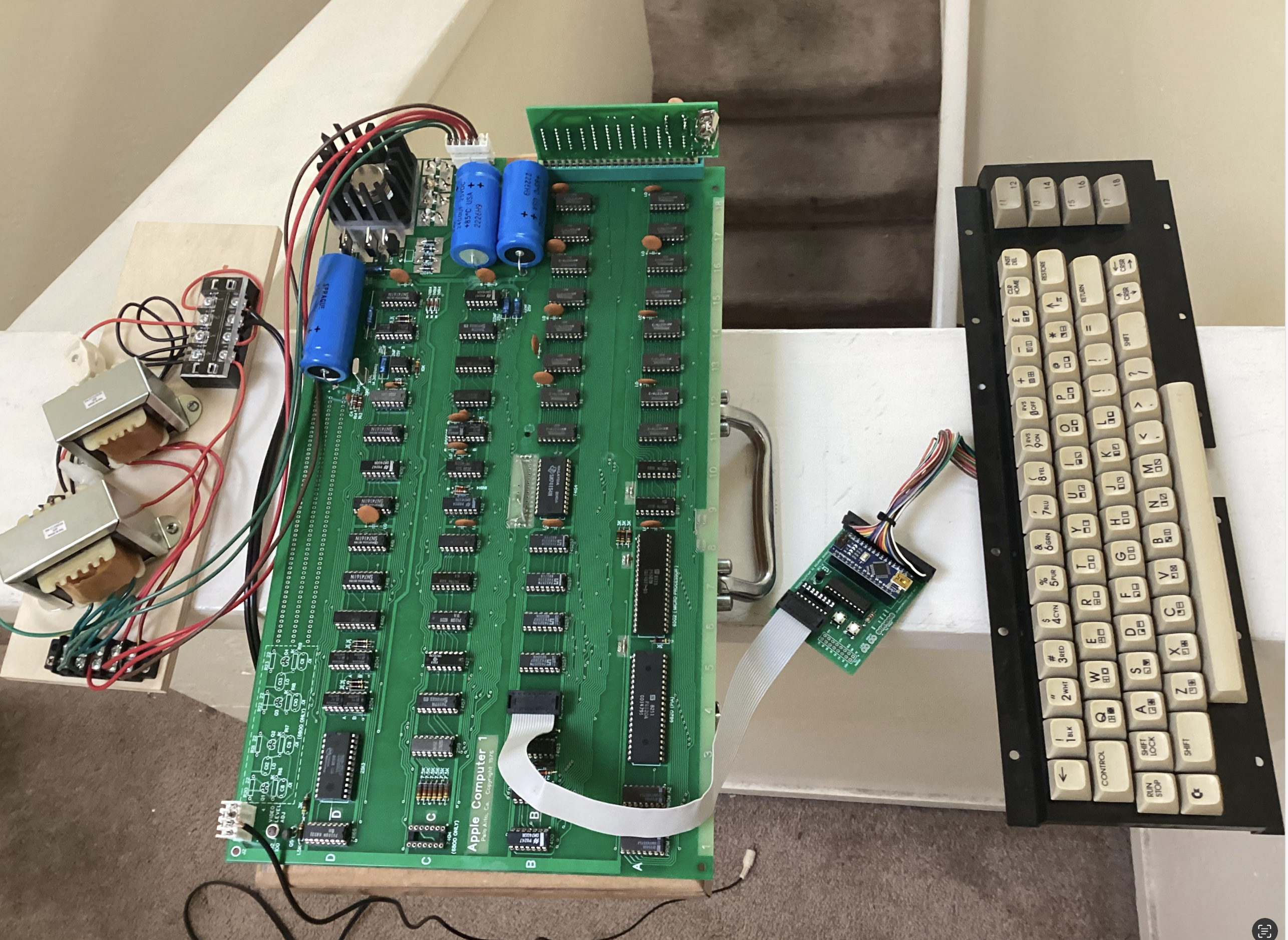
As I said, it works! Of course, it doesn't get along with any of my LCDs, but that's OK, most of them don't like my Apple IIs either. So far the CRTs are working fine (though my Amdek has some weird geometry). My only issue is the encoder for the Commodore keyboard. If I type something before clear-screen and reset it will add characters to the screen, mostly dashes, and won't stop until I hit a key. Then clear-screen and reset work as expected, and the keyboard works normally.
Forgot to ask, but I noticed that the ROMs and CPU get really warm during operation. I've heard others mention the ROMs getting hot, but I've never seen this with a 6502 before. Is that normal?
A quick look: the four resistors below the capacitor need to be of 1% tolerance, these are not 'regular' resistors. Double check the two transistors, are they oriented correctly? The MPS3704 go the other way around. Could be the cause of the failure.
Hello DistantStar001,
unfortunately at the moment I can't help you with your ACI issues (I'm sure others will).
Regarding the Appledore adapter: yes you are right, there was a bug (or rather, a missing Strobe initialisation at boot, shame on me...) in the microcontroller code.
I knew of its existence, but had completely forgotten to fix it until you reminded me, for which I'd like to thank you.
I think I have solved the problem, but I kindly ask you to try to update the firmware.
The GitHub repository has already been refreshed with the fixed code.
https://p-l4b.github.io/appledore/
Sorry for the inconvenience, enjoy your build! :-)
Regards,
Claudio - P-LAB
What exactly does not work for you? Does the answer A9 appear on the screen when you type C100?
Yes, the computer returns C100:a9* as expected. The issue is that it won't load tapes and just hangs there after the tape ends instead of dropping me back into Woz-mod. When I reset and check the contents of E000.EFFF the memory is blank.
No problem. And will do.
You wouldn't happen to have the part numbers for these or know where online I can get them? I'll be stopping by my local electronics store tomorrow, but on the off chance they don't have them, it would be nice to know where to go.
Also, thanks for pointing out the transistors. I've got some spares, so it should be an easy fix.
Well, then maybe it's not the card... ACI is not a particularly handy card, for successful downloading you need to adjust the sound level for almost every audio file. I download programs from my MacBook via the free VLC player. The volume level is always less than 100%, 80, 90... I'll give you a link to my audio files folder, there's a text document with all the addresses. It's in Russian, but I think you can figure it out.
https://disk.yandex.ru/d/PkeDgYyDib1gqw
The original board used 1% resistors 10k RN55D1002F, but if you don't care you can use modern ones, they should be blue, not brown. I don't think that can be the reason though.
04 ACI NTI.jpg
So I was just noticing that the transistors on my ACIs are 2N3904s, not the MPS3704s seen in the originals. Could that be my problem?
I've tried adjusting the volume. But by the time I got to below 50%, I had to assume it was something else.
Just so I know, what are my alternatives? SD, Compact Flash? I have to imagine that there's something out there, but I don't know what it is or where to get it.
2N3904 is a proven modern replacement for MPS3704, a complete analogue. I have put both of them, there is no difference.
Type on your keyboard
C100.C1FF
Then check what you see on the screen Тест PROM ACI from the text file in my folder.
Take a picture of how you connected the wires to the audio jacks on the back of the board.
Screenshot 2023-06-29 at 7.38.56 PM.png
Screenshot 2023-06-29 at 7.39.17 PM.png
Not sure where to find your folder (I sware I'm better with tech that's my age), but here's a screen clip. Hope it works.
IMG_3647.mov
In the second picture it looks wrong, both audio jacks should be connected the same way and a piece of wire should be ringing with the long lobe of the audio jack (on the back side of the board you have it on the right). Check it out. I'll add a picture of my connection just in case.
I gave you the link to my folder in the previous reply, there's a lot of useful stuff there, I've been collecting for several years..
IMG_20230630_075910.jpg
Found it. Sorry, I got confused and thought it was being hosted on this site. Comparing the video to the text it would appear that the computer is listing the ROM contents correctly, and everything seems to match.
As for the second pic, I checked the continuity on them and they seemed right, but it's a simple fix. However, for the moment, I've been using the first board as that's the one with all its components, but it's still not working. As I said, I'll be stopping by the electronics shop tomorrow, so I can get the missing bits then. Maybe when I get both boards populated, I can test more reliably between them.
All right, let me know if it worked or not. We'll fix that thing, don't feel bad!
As for the other expansion cards, the Juke-Box from the esteemed P-Lab is great. So has his SD card, but I haven't tried that.
In general, not much software for the Apple-1, I would say only 40-50 programs, of which 1/3 is the same type of program which aims to guess a word or number. Some more quite complicated, you need to get a degree from Harvard to understand how to play. Really simple and interesting programs no more than 10... See my Apple 1 EPROM Interface project, there are no hard to find parts and you can build it in 30 minutes.
https://www.applefritter.com/content/apple-1-eprom-interface
Regarding the transistors; if you are using a different type that is interchangeable make sure the orientation is correct by checking the pinout of the transistor. What I mean to say is it could be that the orientation is correct on your board if you not use the 'original' MPS ones. Check the datasheet of the transistor you are using and see if the pins match with the schematics.
from DistantStar001's post #9:
"Yes, the computer returns C100:a9* as expected. The issue is that it won't load tapes and just hangs there after the tape ends instead of dropping me back into Woz-mod."
Uncle Bernie says:
You probably meant Wozmon, not Woz-mod. Hanging is is normal for a failed ACI cassette load. Not very user friendly. Root cause is that there is no timeout timer. ACI firmware just waits until enough read pulses have been seen to fill the memory region. If there are fewer read pulses than required, the ACI will wait forever for the missing pulses. In my extended ACI routines (started with C500R) I tried to mitigate this at least a little bit by adding a trailer. So there are more pulses on the cassette tape than absolutely needed for the memory region to be read. However, this measure goes only so far . . . it can tolerate a few missing read pulses (i.e. dropouts on the cassette tape) and then it would throw a checksum error, but still would "hang" if more read pulses went missing than added by the trailer. And with a measly 256 bytes of PROM added, you can only add so much . . .
from DistantStar001's post #9:
"When I reset and check the contents of E000.EFFF the memory is blank."
On the Apple-1 there is no such thing as "blank" memory. It is never initalized and hence it's filled with random garbage, depending on the power up state of the DRAMs. Mostly, $FF and $00 in certain groups. I shall now assume you try to load Apple BASIC into $E000 to $EFFF. Note down what you have at $E000 to $E007 before the read command. If you find the same data there after your read attempt, you got no read pulses at all: the ACI firmware never started to deposit anything in that memory region.
from nijssen's post #2:
"... the four resistors below the capacitor need to be of 1% tolerance, these are not 'regular' resistors."
Uncle Bernie comments:
The 1% spec probably was an attempt by Woz to make the ACI work better. The attempt failed. No amount of matching in these resistors can undo the catastrophic AC impedance mismatch which suddenly occurs at the comparator inputs when the cassette recorder is plugged in.
His next attempt at a remedy probably was to increase the hysteresis. Which makes the ACI very finicky and sensitive to the signal level / volume knob setting. All the "not enough volume" problems with the ACI come from the huge hysteresis needed to tame the comparator.
The "Gen2 improved" ACI for which I made the PCB with the many small SMD parts has a completely different and impedance balanced input circuit. Which allows for a much smaller hysteresis. Which brings much higher sensitivity and robustness against "volume knob" settings. I provide the rare and expensive DALE RN55D1002F resistors just for authentic looks. The new circuit doesn't need no 1% matching.
The big questions to find help are:
1. Did you ever get any read pulses at all (LED would light when cassette recorder or signal source has enough signal).
2. Did you ever read APPENDIX 10 of my "Tips & Tricks" pdf which I offer for free to every builder of my kits ?
Note that there are different versions of "improved ACIs" out there: Gen1 hand wired, Gen1 modified PCB, Gen2 modified PCB with a SMD Zener diode, and Gen2 modified PCB with a SMD shunt regulator (LM4040). The latter two look identical (SOT-23 package) but must be mounted differently. You can't mix these parts up and you must follow the right instructions on how to mount the SMD parts, and which leaded components are replaced in Gen 2 (the hysteresis resistor goes up from the original 47k to 300k - and 300k won't work in the original ACI circuit).
IN CASE THE LED NEVER LIT UP
I'd suggest you first try to find out what went wrong with the Gen2 version. I noticed you did not use the parts in the kit to build it (the "SCC" marked PCB in your first post). Bad karma ! If the transistors you did use are 2N3904 (from the kit) you have them soldered in turned 180 degrees, and the collectors and emitters are exchanged.
Now the whole Darlington configuration has a current gain of maybe 25...36 instead of the gain of 127000 that was wanted.
Not wonder the LED would not light when that circuit is driven via a 5.1 MEG-Ohm base resistor !
If you used other transistors then you have to check which EBC orientation they have. Many European small signal transistors have the opposite (CBE) from the 2N3904.
The only solace is that in this circuit, by putting them in backwards, they don't get killed, unless you fry them when desoldering. Here is a desoldering trick: use a thicker (spade or screwdriver) tip on your (hopefully temperature regulated) soldering pen and add solder to make a solder blob comprising all three legs of the transistor you want to remove. Then, when the blob is molten, gently pull the transistor out from the opposite side, using tweezers or a similar tool to grab them. Having the PCB in a vise saves you the need to grow a third arm. Cleaning the solder from the holes can be done with solder wick or a sharpened graphite pencil tip. Do not use these spring loaded suction pumps. If you have one, throw it into the trash. Their recoil tends to destroy PCB traces. They are dangerous toys. Avoid ! Better EXTERMINATE them.
After you got the components soldered in the right way, the LED should not light when the Apple-1 is powered up. It may briefly light up during power up. Now, if you touch the far side (near the PCB edge) of the 5.1 MEGOhm resistor with your bare finger, the LED should light up (a few electrons are enough, as the circuit has a current gain of more than 100000).
At that point you can test the circuit with a cassette recorder or any other signal source. When you plug in the cable to "FRM TAPE", the LED should not light. When you then turn on the signal (playback of any recording, even music) then the LED should light. Use a medium volume setting at least.
If the LED refuses to light up, then take a voltmeter and check the voltage on the left hand leg of the 10k resistor closest to the "M" of the "FRM TAPE" against circuit ground (at the big rings around the 3.5mm connectors). It should read 2.5V +/- a few 10 mV. So anything from 2.47V to 2.53V is OK. This is the bias voltage for the comparator inputs, which is the heart of the Gen2 improved circuit. If the voltage is off by too much, the circuit won't work.
This is all I can adviase for now. Looks like many mistakes have been made. But all of them can be corrected. Don't change the 10k resistors yet. The Gen2 circuit should be robust enough against moderate mismatch there. As long as they came from the same tape/reel, even the cheapest resistors would probably do. They may have a 10% tolerance band but the matching between four individuals from the same tape should be much better than that. Unless we were unlucky and got that 3 sigma (or worse) specimen. For industrial production we would of course set tighter tolerance bounds to avoid any rework. But after all, we are hobbyists and have all time in the world ... if need be we can sit there with a pile of resistors from the same lot and measure them to fish out those magnificent four which match as needed. Oh, and 250mW 1% metal film resistors got so cheap - if bought in larger quantities - that it's pointless to stock any wider tolerance bands for the electronics lab. Oldtimers may object that if you have wider tolerance bands then you can fish out the right value you need. This was maybe true back in the 1950s and 1960s, but then the manufacturing process control methods got so good that you never get a spread over the whole tolerance band in any given lot of components. But you still might find a funny statistical distribution - such as one where there is a crater in the distribution. In this case the crafty manufacturer "stole" all the premium specimen with tighter tolerances from that lot.
- Uncle Bernie
Sorry. This is more or less what I meant. I just figured that blank was easier. But yes, each line will consist of either FF or 00, alternating every two lines. Although, typically, $E000 begins with a D5 or D7. The issue is that the memory is unchanged after the load.
No. But if the lower jack is empty, it will light up if I touch the contact.
Fixed. I ended up replacing them to be safe. I'm not sure if the originals were ones from the kit (I don't think so as the originals were slightly smaller as I recall and ended up on the other board), but I did check the pinout of the replacements to make sure they matched.
Have them. Hate them! Honestly, I've never seen them lift a trace, but it's 50/50 that they actually clear a hole. And regardless, they spray bits of solder dust everywhere. Solder braid just works better. And it's cleaner.
It's doing that now.
The voltage is too low, only 2.4oV.
Side note, I already replaced the 10k resistors before I saw this post, but I appear to be closer, so it doesn't look like it did any harm.
In post #19, DistantStar001 wrote:
"The voltage is too low, only 2.4oV."
Uncle Bernie's response:
So there is something wrong. With the ACI out of the Apple-1, use an ohmmeter in the 2k setting to measure the resistance between this node and the +5V rail (i.e. pin #14 of the 74LS74).
It should be 1 kOhm if you have the shunt regulator version of the Gen2 ACI, and 120 Ohms for the Zener Diode version.
Please send me the answer via Personal Message (send PM button for UncleBernie). We do not want to clutter this thread with too many possibly embarassing questions on what, how, and why your Gen2 ACI build went wrong. So far, everybody who followed the APPENDIX 10 instructions in my "Tips & Tricks" pdf had success and the Gen2 ACI worked fine. I received no complaints, ever, except for a few builders who struggled with the SMD parts ("bird feed"). But even those did work.
- Uncle Bernie
The mistakes made in this ACI build (which now works after some hints by messages) were:
a) not using the original component set in the kit
b) transistors put in backwards / turned 180 degrees
c) wrong hookup of the 3.5mm jacks
The first two mistakes are avoidable, just follow the "Tips & Tricks" pdf every builder of my kits can get.
The third mistake is so rarely made that I did not put a photo of the jacks in. Well, even I can learn.
So here are two photos how to put in the jacks correctly:
PDRM4055.JPG
And here the top view:
PDRM4056.JPG
Note that I did connect the two otherwise unused solder eyelets with a short piece of wire.
This is optional, but if you do, it helps with two issues:
- these Chinese made 3.5mm jacks do not have the quality anymore which they had when the factory was still in Japan. The Chinese workers do not crimp the assembly together properly, and so in most specimen, it's too loose and the various contact rings can rotate. If they rotate too badly, you will get shorts.The added little wire discourages that mishap.
- There is a switch (alas, a lousy one) in the jack which, when the wire is added, it will ground the tape input when no cable is plugged in. This keeps the LED from lighting up erratically due to a floating input, which can happen with the Gen2 improved ACI, due to the changes in the comparator circuit (for an explanation see below). Because the switch is so lousy, you may need to inspect it with a magnifier to see if it really is closed when no cable is plugged in, and if there is a gap, carefully bend the switch tongue such that it does make contact. A little goes a long way - don't overdo it !
Another trick I have used visible in the photos is to solder the jack to the ground rings on the PCB at some places in the circumfence. This is tricky as it could melt the plastic washer, so don't try unless your soldering skills are fully developed.The advantage of this measure is that it prevents the whole jack to rotate. The issue is that the ring nut on the jack cannot be tightened enough to keep everything safely in place. The plastic washer conspires against that.
So you see, these jacks are low quality junk. But you can't get better quality ones anymore, which still would fit into the ACI. We can be glad that somebody in China still makes these now long obsolete jacks at all. There exist higher quality 3.5mm jacks within a plastic shell for PCB mount. But these are useless for the ACI, as they don't fit.
- Uncle Bernie
ADDENDUM FOR THE CURIOUS: EXPLANATION OF ACI GEN2 MOD INNER WORKINGS
It all boils down to something called "impedance balancing in differential circuits". In the original ACI, it looks as if Woz tried to achieve that, by specifying 1% resistors in the comparator input biasing circuit. This attempt failed miserably and the money for the 1% resistors was utterly wasted. We still use them nowadays to have the same "looks".
What happens when the cassette recorder is plugged into the original ACI, the impedance balancing bought by the 1% resistors is all but gone and the cr@p on the polluted power supply and ground return lines now is "seen" by the differential comparator inputs as a differential signal, and not as a common mode disturbance which it would reject (so some extent, see the CMRR spec in the datasheet). So the comparator output chatters erratically. Most likely, Woz' next band aid step was to increase the hysteresis of the comparator until the chatter was gone. Which explains the poor sensitivity and poor reliability of the original ACI.
When I decided to root out the problem with the ACI (you can regard my Gen1 improvement as a lazy intermediate step, where I tried to bring at least some relief with minimum number of changes to the PCB and minimum number of components added), then I redesigned the input circuit to have (almost) perfect impedance balancing on the comparator inputs for the actual use case, which is with the cassette recorder being plugged in. I wrote "almost", because inevitable imperfections arise due to the unknown impedance at the cassette recorder output, and the contributions of the audio cable parasitics (don't make it too long, one builder tried 6 feet of audio cable across the living room, to the stereo set, and it didn't work, although your milage may vary).
Now, with this (almost) perfect impedance balancing, I was able to decrease the hysteresis, which gives it a higher sensitivity to the audio signal, and this greatly contributes to the higher readback reliability of the Gen2 improved ACI. One builder has even made a very elaborate investigation of the Gen2 improved ACI vs. the original ACI:
https://github.com/flowenol/ACItest
Alas, there is a downside of the Gen2 circuit: with it, the impedance balancing now goes away in the non-use case, if nothing is plugged into FRM TAPE, and consequently, the comparator output may chatter, and the LED might light up, which causes no harm, as the ACI is not in use, but it may be confusing / annoying.
Common sense and logic tells us that Gen2 has to be the preferred solution: the Gen2 improved circuit is impedance balanced when being used for tape readback (cassette recorder plugged in) while the original ACI is impedance balanced only when not being used (nothing plugged into the FRM TAPE jack). We can't have impedance balancing in both cases (plugged in / unplugged).
Unless we use a switch to actually ground the "FRM TAPE" when nothing is plugged into the jack.
Hope this explains the "why" behind all the above. As you can see now, even a humble ACI, which is a quite simple circuit, has some pitfalls lurking when exposed to the real world. Digital designers (even great ones like Woz) should better stay away from messing with analog / mixed signal circuits. Very few electronics designers can work successfully in both domains. And then, there is a third domain, RF / microwave. Those designers who truly master all three domains can rake in mind boggling salaries. Just sayin', nowadays pure digital design is a commodity, so if you are a young aspiring person looking for a career in electronics design, you need to expand your skills into analog and RF, too.
- Uncle Bernie