Related to my other post regarding the repair of my Apple II Rev 0 computer at this link https://www.applefritter.com/content/my-apple-ii-rev-0-psu-info is my solution for fixing keys that did not work.
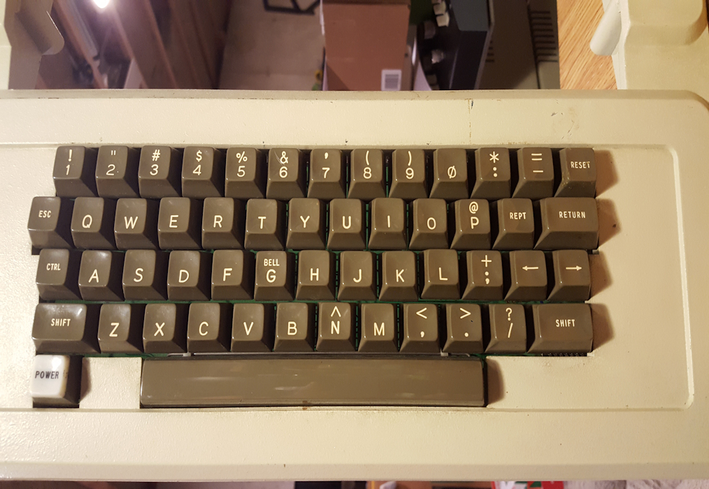
After powering up the computer with no I/O cards, I hit Reset and got the expected VGA dispaly. I did a key test, pressing each key down the rows of keys and found some keys didn't print on the screen, and some keys bounced resulting in several characters being printed on the screen.
When trying to type in the familiar Monitor command to do a memory test I found that six keys didn't work 98% of the time. I eventually succeeded in entering the command line and found about 8 memory location errors. I decided to focus on the keyboard first.
I had the case/keyboard already removed from the main board/case bottom, so removing 4 nuts holding the keyboard PCB to the case was the next task.
This first photo shows my key continuity test setup with my Fluke set to low impedance and to audibly beep on a short circuit.
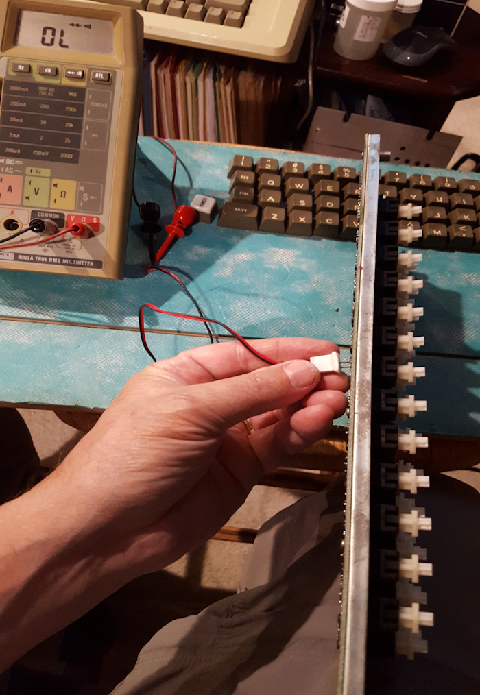
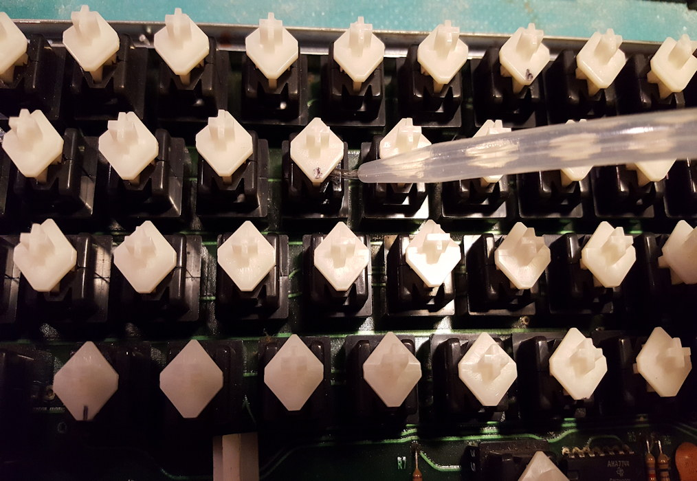
I clipped a two pin male lead connector from an old IDE drive connector and cut off the plastic lips that surrounded the two pins. The two pins where the same distance apart as the key solder pads on the PCB. This made for easy probing of each key, holding the two pin probe in my left hand and against each key pad and with the keyboard sitting on its edge. This left my right hand free to press the key being tested. The squeeze bulb shown below is what I used later to dribble a few drops of 99% Isopropyl alcohol into the keys found faulty.
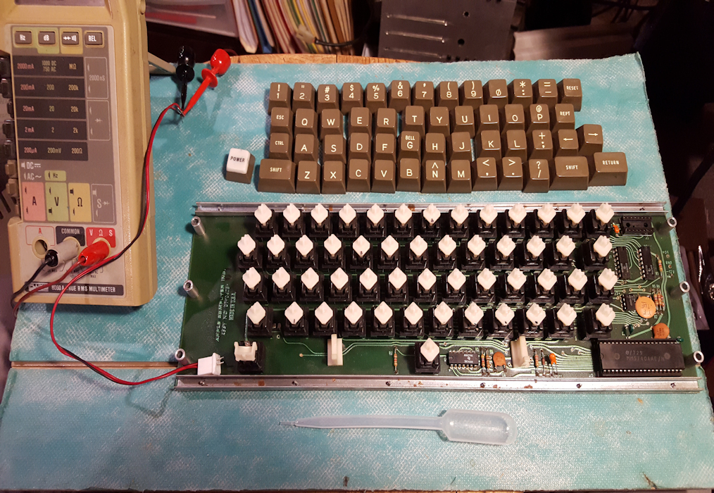
Here is my testing setup:
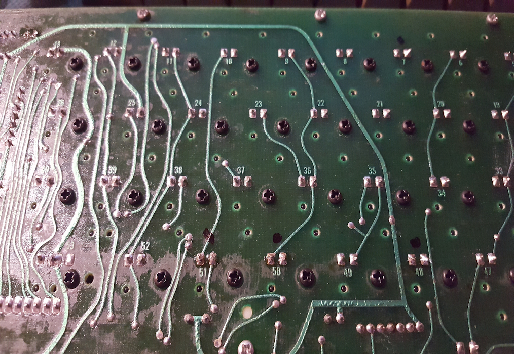
When I found a keypress that didn't produce a beep I marked that key with a black Sharpie pen on the pad side of the PCB. Keys 7, 51, 50 and 58 are shown "marked" here.
With the keys with no or intermittent contact I then filled the squeez bulb with alcohol and dribbled some drops at the edge of the white plastic "push-button" and the black plastic base, shown here:
Immediately after dribbling alcohol into the key I depressed the key(s) multiple times to give the alcohol a chance to clean the contacts. When I then probed the defective keys again they all made good contact.
Problem solved.
Nice job! I'd like to know if the keys still work after a week or two. I've used electronic contact cleaner imstead of the alcohol and in a few cases I've had to re-apply the contact cleaner after a couple of weeks.
I'll let you know. I didn't have any contact cleaner except for Deoxit for faders and that stuff is too thick.
The enemy to these old keyboards is idle time.
The longer they sit the less reliable they are.
If they're used regularly they seem to be perfectly fine, but if they sit for a few months unused, they start to fail due to contact oxidation.
No doubt. Mine sat in it's Apple II brown zip case from 2014 to 2023 with no use, in my air-conditioned basement.
DeoxIT D5 made things worse. ;-(
I went from only 5 keys not working initially, after my ol' baby sat idle for 9 years, to cleaning them with 99% alcohol as mentioned in this thread resulting in them all working, to thinking I would play it safe and clean them with DeoxIT D5. After several attempts with DeoxIT not achieving positive results, I've dropped to 24 keys not working. Bummer.
Maybe the Cherry MX 3D print conversion is may only bet. I guess I will reach out to LR514.
Given the way the switch membranes are constructed I can see how contact cleaner can get between the two facing Mylar membranes making it harder for the two copper contacts to be pushed together by the downward movement of the key plunger. Maybe with time the cleaner will evaporate. (Just an observation though, well see.)
Quite possible.
The only reliable way I have found to reliably correct poorly contacting key switches is to take them apart physically and clean the internal contacts.
This is an extremely delicate operation, and I have had to replace entire key switches as a result - sometimes they don't want to come apart. Sometimes they get damaged. Sometimes they just don't respond to cleaning. Sometimes the metal foils don't have any springback. Sometimes (insert myriad problems here) happen.
But if you want them to work reliably, sadly this is the only way that works.
@baldrick, I appreciate your comments.
The alcohol flush worked a treat, allowing time for the flush to evaporate. D5 was an abismal failure, so now I'm trying to coax as much residue out of the failed switched as possible and "dry" them. So I guess I get to try DC-51 'forced disassembly and cleaning' if all else fails.
DeOxIt works beautifully to remove oxidation.
But it needs to be flushed out. And often needs to be followed by mechanical removing of the residue with a swab.
Simply squirting in some and hoping for the best isn't a good method because the contacts in the key switches don't "wipe" each other as they would in a plug or a sliding switch, they just press against each other to make contact.
This off course assumes one can get the black plastick housing to separate at the seam.
Update: After desoldering and removing one key I find that the terminal pins on mine are curved semi-circular pins and not solid pins. One interesting note however, is that the key I removed didn't work after DeoxIT (it worked prior to Deoxit), but when removed it works 100%.
While I don't understand a comment like this without additional details, I almost had ah-ha moment this weekend working on II+ keyboard.
But in the case of the II+ keyboard, I'd say any cleaning fluid is not a good idea when sprayed on the stem. When I fully disassembled the keyboard I discovered the plastic shielding just grabs and pulls the liquids under the plastic. Will it ever dry out? I have no clue. So after fully cleaning and reassemblying everything the keyboard is great, but the extra cleaners (IPA and Deoxit) didn't help the cause. But, I don't think deoxit as a cleaner does anything to the circuit, just made a mess in this ccase. So what caused you to say this?
Since 1978 through 2014 I never had an issue with my Rev 0 keyboard. All keys just always worked just fine. It was always packed away, wrapped in paper, in a box or zipped up inside its Apple travel cover when not in use.
When I decided to sell it early this year, when I fired it up the PSU was dead. I put in a spare Astec. It wouldn't boot, but after reseating some chips, insuring the Reset line pulled low at the CPU it would start in Monitor. All but 4 or 5 key worked as I discoverd this when trying to type in the memory test monitor command line. I pulled the kbd , ohmed out all the key and confirmed the 5 that were intermittent or not working. As posted earlier in this thread I dribbled isopropyl 99% down the stem and these keys came back to life...worked great for several hours without problem.
Someone mentioned they had done this manner of cleaning and found that after some time they stopped working and recommended contact cleaner used for switches. I've not used contact cleaner for switches for many decades when we used to use them for TV channel switches or yore. My research seamed to indicate DeoxIT D5 was a solution. Not knowing the inner workings of the DC-51 kbd switches, I squirted some down every kbd stem,exercising all the switches for minutes, and gave it time to dry. I ohmed out all the kbd switches on the backside of the PCB and now I had something like 28 switches that were DEAD, disfunctional. 99% alcohol worked fine, DeoxIT D5 did not.
Heavy, repeated doses of 99% isopropyl revived a few switches but not many. Desoldering two switches confirmed either dead contacts or intermittent switching that adding side or more down pressure on the stem would yield.
Then I researched how these switches are mechanically designed by finding some threads on this forum. This made me realize that residue from cleaners could get build up on the mylar separator and other materials in the switch "sandwich". With a magnifying loop I could see a copper strip that was held at the top end of the key plunger on the side of the plunger that faced the kbd copper ribbons. So that made me dig more into how to take these switches apart without damaging them.
Just within the past hour I succeeded in opening up a DC-51 switch, separated the sandwich, cleaned residue, quite honestly the copper strips looked quite clean,. There was some light blue, caked on residue on the thin, flat metal plate and at the base of the two copper contact sheets. More on this later. I just struggled with coaxing all the pieces back in place inside the two case halves. I'll be posting photos this adventure and discoveries made to this thread very soon.
For those who have already taken DC-51's apart, cleaned and put them back together, I'd like to know what you used to bond the two black switch cases back together. Super glue?
It's intesting some of the early switches were ultrasonic welded other snapped together with plastic clips. Obviously the clips are easy to disassemble/reassemble. I"m not clear on the DC-51 construction, but would imagine if you do try to CA glue it, be carful you don't want that anywhere but that edge.
One thing that's not well known and happens cuz we all make assumption, is that deoxit just works. It doesn't just melts away build up insteady it needs to be physically remove the corrosion. The thing is, I don't think cleaning anything from those contacts inside those swithces is a job most could do well. They are fragile and easy to bend. I imagine they are easy to deform so the switch doesn't work correctly.
Two random thoughs which may or not be helpful... Deoxit is non conductive, so even if it was wet and pooled it won't create a short. Alcohol is conductive so time to dry can be important.
corrosion.PNG
Those spots are where the key switch made contact with the board contact. I'm not sure if this was the result of use or storage (heating/cooling condensation, etc)This is how it looked after cleaning (and yes I cleaned up the mask while at it since the switch can move the largest landing area can't hurt) since this is a chemical bond even with deoxit I needed to scrape buildup off with a syringe :
cleaned pads.PNG
The switches looked OK, but you can see in one of these pictures that growth likely from a drop of moisture can happen. If it happens at the point of contact that will likely block contact.
clean switch contacts.PNG
swtich corrosion example.PNG
I'm going to give plastic welding a try to rejoin the two key switch case halves.
Good point, DeoxIT Fader is definitely the best for linear or rotary resistive potentiometers. DeoxIT D5 is solely meant for switch contacts.
Your keyboard photos are a world away from the ones used in the Apple II Rev. 0 era that uses the Datanetics DC-51 key switches. BTW, these switch case halves are designed to have up to two momentary switch contacts, but implement only one contact for the early Apple II. As mentioned before the black plastic key housings halves are semetrical and likely ultrasonic welded together. The weld seam line is readily apparent on all four sides but I found the seam line on the bottom side is the one that begged to be "cracked" open with a small chisel (screwdriver) as shown in these next photos.
DC-51-1.jpg
I initially and carefully used a small utility knife with a fresh blade to scribe along the seam line shown above on opposite sides. I used very light pressure which allowed the point of the blade to more easily follow down the seam line and create a light scoring. I repeated down the line 4 or 5 times, each time deepening the score line along the seam.
DC-51-2.jpg
I then positioned the switch housing upside down in a small steel vise and closed the vise down just enough so the switch could just barely slide back and forth in the vise's jaws.
I noticed that the seam line on the bottom side was more prominent and had an inviting divot right in the middle and immediately to the right of the two contact pins, shown below.
DC-51-3.jpg
I held a small flat-blade screw driver in the divot, using it as a chisel, and using the rubber handle of a much larger screw driver as a mallet lightly tapped the top of the "chisel" screw driver 4 or 5 times. This caused the case halves to completely separate every so slightly since the jaws of the vice limited the case halves separation.
DC-51-4.jpg
DC-51-5.jpg
I removed the switch from the vise while holding the case halves together then separated them over my work area. The white plunger and spring popped out along with a "v" shaped, springy copper contactor that fit between two cut-outs in the side of the plunger, shown in the image below. The "v" shaped contactor faced towards the actual switch plates sandwiched in the photo above.
DC-51-6.jpg
The pinkish colored plastic has a "nib" in its middle that is anchored at the bottom. This "nib" is what the "v" shaped copper contactor pushed against when the white plastic key plunger is depressed. The "nib" then presses against two, thinly separated flat, copper ribbons of metal causing them to "connect".
DC-51-7.jpg
This next photo shows the three main layers in the sandwich spread out next to each other.
DC-51-8a.jpg
Each copper ribbon has a cupped extensions that protrudes out of the bottom of the key base. These protrusions are the key switch pins that solder into the keyboard PCB. Next is a series of photos of the sandwiched switch layers. I'm showing both sides of the square mylar with a circle cut-out that the two copper contact strips cross over. On that side opposite the pinkish plastic contact "toggler" is a thin, flat, square metal scquare. The side towards the copper contact strips seems to be coated with a blue "somthing". Below is the opposite side of the mylar with copper strips.
DC-51-8b.jpg
Some minor, flakey corrosion can be seen on one side of one of the copper strips and that was easily wiped off with a Q-tip and CRC QD contact cleaner. The other copper strip was very clean with no oxidation of any kind. I ran a very thin blade between the two copper strips where they would be pushed together in the circular opening and was able to see between them, which was also reasonably clean.
Then I put the switch back together...a long teadious, trial and error process...ohmed out the contact pins, pressed the key plunger and the key contacts closed consistenly. I have returned the switch in between the vise jaws to hold the halves together until I decided on how best to bond them together. I'm thinking plastic welding with a soldering iron.
Any comments are welcome.
Yes, the II+ keybaord is a freakish design. At first I was totally surprised but as I tore it apart and analyzed the design I think it's interesting. Not sure if if this or mountable switches is a better design, but one is definatley easier to replair.Does the plate with the blue get sandiwched between the clear plastic part with the contacts? It looks like there's a bit of blue left on the clear that matches some missing blue on the other piece?What I can't figure out is does the blue coating create a slight trench which acts as an air gap between the strip next to the actuatior (red finger)? Does the small loose leaf spring looking thing get mounted in the plunger as a spring to push the actuator which in turn allows the plunger side trace to make contact with the plate which has continuity wiht the second lead?
I see all the parts just not clear how they all are stacked. I'm also wondering if what appears to be a trench in the blue should be a clean and clear path?
The picture on wikimedia doesn't answer question, but does not show any blue coating on the plate piece.
File:Datanetics DC-51-01 -- disassembled, inside views.jpg - Wikimedia Commons
I found some better pictures here, which I think suggests there shoud be a clear strip in the blue if the blue is a non-conductive coating. The circular hole is similar to what's used in the II+ keyboard but on a full-keyboard scope with many holes for the contacts. But it appears you know this tread....
Cherry MX to Datanetics DC-51 Keyboard Switch Adapter | Applefritter
Plastic welding (with methyl-ethyl-ketone) works well with ABS. It does not work at all with polypropylene or nylon. If you put a drop of solvent on a flat section of the plastic and use a metal probe to push on it, ABS will soften and become pliable.
If you dissolve a few grams of powdered ABS in the solvent it makes it thicker and stickier, just what is used for plastic modeling glue. Actually they may be thickened with just polystyrene.
As far as heat welding using a soldering iron, that's another possibility, but it's far easier to overheat the plastic. Picture your soldering gun/iron just sinking into the plastic, vaporizing it and leaving a crater...
The blue "coating" may be a copper oxide from an electrochemical reaction between the switch contacts and the backing plate.
The Wikimedia photos don't show all the parts separated apart. LR514's images are more accurate.
In my last photo of the switch disassembled we have at the very top the half of the plastic housing that holds the "sandwich" of pieces. Immediately below is the thin metal plate, normally silverish in color, but the side of the metal plate that faces toward the camera has a blue copper oxide coating with yes, what looks like a long, rectangular void running up the middle where the copper strip that faces the metal plate would rest close to it. Next is the mylar square with a circular cutout. On each side of the mylar square are mounted the two long, rectangular copper strip contacts. The mylar between these two copper strips creates an air gap and prevents them from touching each other. Below the mylar contactor strips is the pinkish square with a "tongue" actuator tab. These three items are sandwiched in that order and slide into a slot that is as long as their square shape is and as thick as the three sandwiched together.
I think the other comment by @robespierre was correct in that the bluish color is likely a copper oxide coating formation from decades of the metal plate and the copper strips being in close proximity to each other. I see no other reason or purpose for this coating. And yes, there is a trench of sorts in the blue coating that is in line with the copper strips.
@robespierre, thanks for the reminder of methyl ethyl ketone.
I've disassembled and repaired some of these keyswitches on my own keyboard. I'm sure that the blue layer is not oxidation, it looks to be a plastic film over the backing plate, but with age it seems to crumble and small pieces can get between the contacts. I think it's there either as an insulator or to provide some damping for the pressure against the contacts.
To get the switches apart, I found that a pair of circlip pliers (which have small round tips which spread apart when squeezed) inserted into the two holes in the back of the switch body, work well to pull the two halves apart. Using a blade risks slipping and causing damage to the delicate contact assembly. I have had mixed results with these switches, in some cases just bending the brass V-shape spring to put more pressure against the contacts worked quite well. In other cases I found that putting a small square of paper behind the contact assembly as a shim helped to make switching more reliable. I haven't tried disassembling the sealed contact layers, but that might be my next step as I still have a couple of switches I'm not happy with.
To close the switches back up, I clamped the halves together then put a drop of cyanoacrylate adhesive on each side and let it seep into the crack between the halves. I didn't like the idea of adding glue before putting the halves together, and risking it getting where it shouldn't.
Thanks for your input. I'm glad to hear CA glue works well because it was my first choice and preferrence since it could, when used gingerly, allow the switch to be cracked open again due to its brittleness.
I've only seen the photos from LR415's post of the bluish coloring on the metal plate and of course, the one of mine I just opened recently. I agree, that mine, at least appeared crumbly , almost crystaline in some places, but was in fact quite well adhered to the metal's surface.
My immediate observation was that focusing on the bending the v-shaped spring so it applies more pressure and/or with the pinkish plastic "tongue" the spring presses against seemed to be the best "refurbishing" strategy.
I have circlip pliers like you mentioned, I may give them a try on my next key switch.
@Silicon-Surfer, when you say you "putting a small piece of paper behind the contact assembly as a shim...", do you mean behind the metal plate?
Yes, I cut a small square of paper a little smaller than the plate and slipped it between the plate and the plastic of the housing. In some cases I used a couple of layers. It's really trial and error with the body clamped back together and a meter on the pins to see what works. This seemed to reduce the resistance with some switches and helped with repeated characters.
I agree about "not having glue get where it shouldn't", but hasten to add that is not likely using MEK to weld ABS. The solvent is very thin and is absorbed into the plastic very quickly. Just putting two pieces of ABS close together and "painting" the interface with MEK will cause the resin chains on both pieces to move about and get intermingled. This can be repeated over and over, until the line between the pieces disappears. The bond develops strength as the solvent evaporates.
A side effect is that the surface texture of the plastic pieces is "melted" if that is a concern. On objects like computer cases it's better to do this on the inner surface.
But as I mentioned in my previous reply, only ABS works this way. Other plastics I have tried to repair using solvents have been failures.
MEK is available in 2oz brush bottles under the "Plastruct Plastic Weld" brand. Incidentally, MEK is not highly toxic but some amount of ventilation would be a good idea when applying it, as well as keeping the bottle capped to minimize the fumes created. It's a bit of a dance to get the brush cap from the bottle, wipe inside the neck to avoid dripping, and then transfer the solvent to the bond line before it evaporates. One technique is to unscrew the cap but leave it covering the bottle while working.
Plastruct sells another 2oz brush bottle called "Bondene" with a different solvent, dichloromethane. I don't like it as it is much more toxic and evaporates almost instantly. It is very difficult to get the solvent where needed before it evaporates. On the plus side, it can weld more different plastic resins together and the bond develops strength faster.
I'm with robespierre, if ABS there are ways to apply acetone or other MEKs to the surface without getting it all over the place. But... ventilate for your safety.I just don't know that these cases are ABS, never tested myself. The "bondene" also mentioned is Plastruct's option, but I beleive it's also only meant PLA.
If there are slide in clips on the switch, I wonder if the case is something else. PLA is fairly ridgid, while it can flex, I don't know if it's good to use as a bendable clip. I can ask some ME friends thst know all the plastics.
I originally thought the blue coating did look like a thin non-conducitve coating, but there's not much to support that, expecially if non-conductive I don't see how the switch would work. Unless there's a trench. =)
clean coating.PNG
blue coating example.PNG
As to the sealing, I'm not sure I'd take chances with melting (neither chemical or heat), but instead I think the best option and requries some dextarity, with switch in hand under slight pressure (small open gap between pieces) I'd lay down a very thin bead of CA into the gap (it's got low viscosity like water and should easily flow into the gap), with all 4 sides done clamp 'er down and hit with CA accelerant (like BSi) and you should be done.
Since I've only opened one key switch thus far, the only other reference I have that is of a Rev.0 kbd switch is the one you just reposted from LR514. Both have the blue coating and I tend to agree the most likely purpose for this coating is to function as a shim to push the mylar contact strips towards the pinking actuator tongue.
And yes, there is definitely an unprotected trench down the middle of the blue coating. The backside copper strip of the mylar strip holder does or can indeed make physical contact with the trench. The metal plate as a little square extension as seen of the left side of the metal plate. What is the purpose of that? Maybe to help "lock" the sandwich in slot? I don't see any electrical reason for it making physical contact with the rear copper strip just where it bends to make the 1st 45 degree angle that leads to the "pin", which is about where they both "could" touch. If you note in the 2nd photo of mine that jeff d posted you can seetwo blue residue patterns that match the missing areas on the metal plate.
The copper strips seemed to be lightly bonded to the mylar at either ends of each strip, because as I slid an ultra thin diameter watchman's screwdrive shaft between the two copper strips, the screw driver's diameter being about the same as the gap between the copper strips, the right end of the strip facing the camera became unstuck but still lay close to the mylar edge. Pushing the end of the copper strip down gently seemed to make it stick down again.
In addition, with this one switch I "operated" on, I entirely removed the blue coating from the one side of the metal plate as it had become uneven in thickness, probably where chips flaked off and landed in other places on the plate. And, as you can see there is a lot of build-up on the right end of the trench. Since I've not sealed the two switch halves together again I believe I will allow it to come apart so I can add a paper shim between the metal plate and the facing mylar side, then test switch contact behavior. As it stands, if I hold the two switch body halves very tightly together the switch does close well.
So I opened up my "patient" and was able to derive this info and clarify some lables that I'd been using in my descriptions.
The mylar shim is really a plastic spacer with a very thin, clear mylar backing and is bonded very well to the plastic spacer with the circular cutout.
Here is a exploded view drawing of the sandwich with dimensions shown for each layer of the sandwich and the copper contact strips. The clear mylar backing together with the plastic spacer together are .008" thick.
20230701_160146c.jpg
I removed the copper strip the faced towards the pinkish plastic actuator tongue. This next photo shows the plastic shim with the backside copper strip still attached and laying down. the metal shim would be where the wood grain sits. The forward copper strip in turned over so the side that normally faces the rear copper strip is up. You can see some dirty buildup on both facing copper strips.
20230701_154458c.jpg
The thin, clear mylar film is actually on top but it is so hard to photograph so it is apparent. The blue coating that came from the metal plate is also top-most. I can now see how important is is that the angular bent areas of both copper strips stay flat until that emerge from the switch housing. As you can see, me initial attempt to close the housing back up crushed those areas a bit.
Hope this is as elightening to others as it has been for me.
I will post a minor but important correction to my sandwich drawing today, plus add more photo details and drawing measurements on the plastic "tongue" actuator.
On closer inspection I don't believe the copper strip as referred to in this thread all along is copper. From its color it appears to be more like sheet brass or a brass alloy.
First, here is an updated drawing of the sandwich I posted a few threads earlier. The main difference is that I found the clear membrane on the backside of the plastic spacer with the circular hole actually encapsulates the rear conductive strip and intentionally or not insulates the rear conductive strip from electrically contacting the blue coated metal shim. That made me think that one possible explanation for why the blue coating is deliberatly missing where the rear conductive strip resides is to provide a better, more consistant and rigid back "wall" to the rear conductive strip, the intent being to ensure the rear conductive strip does not bow or bend when the front conductive strip is pressed into it by the flexible tongue of the pinkish plastic spacer. This would also ensure a more positive contact between the two conductive strips resulting in a more consistent point of contact during a key press. Also added as an update to my hand drawing are dimensions of the pinkish plastic spacer. Thickness dimensions of this spacer are shown to be .0245" at its thinnest and .025" at its thickest. On a 2nd measurement I got .024" and .0245" respectively since I made this amendment. The tongue's width is the .04335" measurement.
20230702_112522e.jpg
Next are two close-up photos of the pinkish spacer, front first then back. The front side's tongue has a raised square area that may be what provides an extra push to make "contact" and is what is pressed upon by the "v" shaped spring that is held by the white plastic key plunger. The backside faces the front conductive strip.
20230701_222207c.jpg
Note the backside of the tongue has a noticable hump near its tip that is what actually pushed into the front conductive strip. This hump is what adds .0005" thickness to the average .024" thickness of this plastic spacer and but at the flexible end of the tongue.
20230701_222253c.jpg
Lastly, a close-up of one half of the black plastic kbd switch housing. This showed me that there are only a few key (no pun intended) areas that are bonded or glued together between the two housing halves.
Comments and/or corrections and/or observations encouraged.
20230701_222335c.jpg
This is a problem you need to take care of... look back at my post talking about contaminates. you should have noticed the ittty bitty (pin head size) corrosion that was blocking the siwtch from working, that's all it takes. Mine was tiny, you've got carbon (and oxidation) all along the strips, that's a real problem for you. Grab the deoxit and very carefully try to get those two inner surfaces clean. It may not be easy as spray and wipe, this may require scraping and you really don't want to do that without knowing how to do that correctly. Because if you deform the strip you'll only make things worse.
While not a lot of current flows through the swith, in your case I can say this is almost 100% the reason the switch isn't working.
I also think the leg of the copper stip in you last photo is going the wrong way, the front one should go toward the switch, the back side should take the trench away from the swtich.
20230701_154458c.jpg
@jeff d, the contact strips in my photos were probably difficult to perceive detail as focus is not spot on. That you've had success in reviving some of these kdb switches is encouraging.
I posted the conductive strips in a way to show what their appearance was after separation. Good catch on the orientation of the bottom strip! The two sides of each strip shown would normally face towards each other. Believe or don't, as shown they were smooth,with only discolorations, no tiny bumps, not even on the corrosive looking areas, that would prevent the two making contact within the circular window. Even the discolored areas along their length were conductive, less than a tiny fraction of an ohm resistance.
I am certain, however, that this switches failure was due to flakes of the bluish coating wedging in between the two conductive strips along their far end, opposite the pins.
The strips were cleaned after I took the photos, though. DeoxIT D5 and Q-tips or a toothpick with a chisel-like beveled end were used to scrub the strip surfaces and had no cleaning effect. It took a very fine watchmaker's hone to buff them clean.
Since taking this switch apart again to document the parts more concisely, I have not reassembled it to see how it works. I first have to solve one problem which is how to reattach the conductive strip. When the end furthest from the connection pin "popped" loose from the plastic spacer along with the manner in which the other end was freed it sure left me the impression that both ends were gingerly melted down as there was no "glue" residue of any kind evident on any surface.
The saga continues...
As it was highly improbably that I could ever recreate a similar coating on the one side of the DC-51's metal backplate, I pondered over what might be a relatively stable alternative. Then I gambled on a possible solution which I had a plethera of...Monocote Trim, also known as UltaCoat Adhesive Trim made by Hanger 9. The stuff is used a lot in covering and trim material for RC airplanes and it was on the order of the right thickness needed. The trim's adhesive backing is what gravitated me to the idea of using it as it solved the simple question of "how can I make something stick e-v-e-n-l-y on the metal backplate. Here is a photo of the results.
UltraTrimHanger9c.jpg
That is was blue gave me extra comfort ;-)
I layered the switch sandwhich back together using this monocoated backplate and was pleased with the results and how it fit back into the one half of the black switch body. Sorry, no photos of that because of the delicate two-handed process of inserting the white plastic key plunger, it's coil spring and "v" spring for test fitting the upper half of the black switch body. It all went back together so well that I was more interested in clamping the two black plastic switch halves together and testing the switch's contact shorting effectiveness. Viola! Rock solid contact. So I lightly coated where the switch halves join in key areas (again, no pun intended) with CA glue and let it dry over night.
Now, I'll have to let time tell how well this solution lasts.
Next! I have a bunch more to inspect and fix.
I can confirm my switch disassembly method described earlier here worked quite well again.
This time it was far easier to flush out the several tiny "bits" (seen with a magnifying eyepiece and that jeff d emphasized) that were preventing the two switch contactor strips to make connection, by using a blast of DeoxIT D5 aimed inbetween the two contactor strips and blowing out the residual with several puffs of compressed air. Checked inbetween the two strips with the magnifying eyepiece and saw the tiny bits gone. Reassembled the switch, held the two body halves gently compressed together in the small vise and tested continuity on plunger press, viola! I left everything else alone other than ensuring nothing loose was floating around in the switch as the blue coating on this switch's metal plate wasn't any where as bad as the last.
I'm encouraged that this may not take as long as earlier feared...knock wood.
When I took apart the 2nd kbd switch I noticed the side of the plastic spacer that had the clear mylar film across it faced the pinkish tongue actuator. The other side of the plastic spacer had the other contact strip making physical contact with the void in the bluish coating of the metal plate. I'm going to verify and confirm this when I open my 3rd kbd switch tonight.
This would make sense if the true purpose of the mylar film was to prevent contaminant particles from entering the switch internals and thus portentially impacting switch contact reliability.
Looking back at my earlier photos showing my 1st switch halves separation it does appear to me in retrospect that the mylar film does seem to face the pinkish tongue actuator.
So my original and updated drawing of the sandwich seems wrong because of today's observation and I will do another updated drawing and post it soon.
DC-51 Sandwich.jpg
As shown above, the DC-51 kbd switch sandwich is perpendicular to the switch body halves seam line. The white plastic, spring loaded plunger would be to the right of the pinkish tongue and laying horizontal and parallel to the tongue. When the plunger is pushed along its long axis (towards the left) the "v" spring held by the plunger would be moved onto the tongue's tip resulting in the tongue tip pressing against the mylar film and the first contact strip and closing the gap between the two contactor strips. The gap closure distance is essentially the .008" thickness of the Plastic Spacer, the thickness of the mylar film is probably negligible.
Comments welcomed.
Good feedback on my last drawing inspired me to clarify the drawing a bit more. The two contactor strips are actually adhered to the plastic spacer, front and back. The mylar film is adhered (through surface friction?) to the front of the plastic spacer and over the front contactor. I think the thin film, mylar, stiff celephane or whatever it is serves as a dust/small particle protector to keep tiny bits from getting between the .008" gap provided in the circular void that keeps the default position of the two contactor strips separated. To the right of the pinkish tongue would be the white plastic key plugner that sits directly beneath the key cap. The length of the key plunger lies parallel to the tongue's length and moves up and down nearby the length of the tongue.
DC-51 Sandwich2.jpg
More comments welcomed.
This was a challenge to hold and take a photo of it.
20230708_155423c.jpg
The more I see and understand, I think the blue coating does serve as a gasket. So along with the thin plastic sheet between the contact and pimpled plastic lever the interior of the contacts is sealed. I'll assume the interior of the switch was intended to be sealed in a basic way to prevent spilled liquids, or condensation from reaching the contacts. At this points, that's my best guess. I still say the interior sides of those contact plates need to be spotless. The good/bad news is the contact can happen anywhere the pimple travels. This is good because you have more area (not a single point) along a line, and bad because with the longer path it does provide more location for carbon to build when current flows. Even a thin layer of carbon is not conductive. Although in this case I think the blue debris was a major issue.
Just from a chemistry point of view, the subject of contact contaminants will depend on what is present environmentally to react with the metal contact. Air contains mostly nitrogen and oxygen, much lower levels of carbon dioxide and sulfur oxides (although they are present in higher amounts in industrial environments or other places where combustion or other activities put them into the air).
So the primary contaminant is going to be metal oxides (reaction products with oxygen) and to some degree carbonates and sulfides may also be involved. Nitrides only form at very high temperatures so won't be a problem.
There can also be off-gassing from the equipment itself, which can either react with or condense upon the contacts. The big one would be plasticizers from plastic parts, but phenolic resins can also be present on circuit boards and other components, which off-gas formaldehyde.
The usual culprit for elevated resistance on switch contacts is copper oxides. One of the reasons that contacts are plated with silver is that silver oxide is, itself, quite a good conductor, so the contact continues to work even in the presence of oxidation. Gold being a noble metal doesn't form oxides readily so it is also used as a switch plating.
What jeff d surmises in that the interior of the switch was meant to be sealed (or mostly sealed) makes sense to me. And the bluish coating was originally a sealant that has become brittle in some areas and flaked off inbetween the two contactor strips or aggrevated to move by the flushing of contact cleaner into the switch body via the area around the plunger stem.
As a point of clarity, the pimple on the pinkish tongue doesn't travel except to push in and out against the contactor strip it is closest to. The pimple always makes pressure contact in the same place. The entire pinkish rectangular plastic piece that contains the tongue is stationary and held in place by slots in the switch body halves.
In my preceeding photo the thin "V" shaped line that is squashed or splayed out is a spring and held in slots of the plunger. With the key up (plunger at rest as shown in the photo) the apex of the "v" spring in resting on the end of the wide end pinkish rectangle just off the tip of the tongue. As the plunger is pressed downward it causes the "v" apex to slide onto the tip of the tongue thus pressing the tongue's pimple toward the contactor strips. The "v" apex can slide further down the tongue as the key plunger is pressed to its limit and still keeps the pimple pressed for making "contact".
I can confirm that the root cause for the last two switches not shorting with the key pressed was due to a few tiny blue coating flakes laying between the two contactor strips.
After thoroughly cleaning all disassembled switch sandwich components and reassembling the switches they returned to normal function.
With the opening of this 3rd switch I can provide a definitive confirmation that the bluish coating is/was indeed a sealant between the metal shim and the plastic spacer that worked in combination with the mylar film on the opposite side of the plastic spacer.
I've repaired about 7 kbd switches so far and the 8th one I'm working on now had the worst oxidation crud on the inside facing contactor strip that lays against the metal shim. If cleaning inbetween the two contactor strips by flushing DeoxIT D5 between them, followed by gentle whisps of compressed air and finally slipping a piece of clean paper between them doesn't fix the switch, I've found it necessary to gently free the rear contactor strip (the one that rests against the metal shim) from the plastic spacer. Here is a photo of what has been mentioned earlier in this thread of oxidation build-up.
20230715_140123c.jpg
The inner facing surface area on the contactor strip (the one closest to the viewer) clearly shows where it bridges the circular opening of the plastic spacer because of a slightly darker coloration. In this darker area are a number of even darker oxidation build-ups and bluish coating transfer, the worst being near the right end of the strip. The darkest one actually looks like a cliff's edge, and it is!
I abraid the oxidation off with a very fine, flat whett stone as the strip rests on this small watchmaker's anvil until it is shiny, clean it and the plastic spacer with alcohol where it glues back on , glue it back onto the plastic spacer, recoat inbetween the two strips with D5, remove excess and reassemble.
This is a great description of these kbd switches and identifies all materials that make up the switch "sandwich".
https://deskthority.net/wiki/Datanetics_DC-50_series
I am working on a video that shows a method of opening and cleaning the DC-51 switch that worked the best for me. A lot was learned after opening and cleaning over 20 of these. This video show a most reliable solution and will supercede any previous photos or descriptive methods for opening a switch. Lightly scoring along the switch halves seam line is the key.
My Apple II Rev 0. keyboard is finally repaired and fully functional. In all I had to surgically repair about 24-26 Datanetics DC-51 key switches and replaced 7 of them with new-old stock I found on Ebay.
What a journey, phew!
I still plan to post a YT video, as a final post to this thread, of my DC-51 key switch repair methods just as soon as I can complete the video editing process. I hope to have it finished by the end of September.
My Apple II Rev 0 lives once again with a working keyboard, 48KB of tested and verified DRAM and the FP Language card in Slot 1. Yeah!
That took a while, glad you got it done!
Well in fairness, some of that time was procastination because of the tediousness of it all. ;-(
Thanks for your tips.
It is unfortunate that we cannot deleter/remove posts on this forum, at least I've never seen a way to do this. I mention this because in post #16, the 3rd and 4th photos of mine, especially the 4th photo should be deprecated.
From my experience after I posted how to "open" a DC-51 key switch...DO NOT EVER use a small flat blade screw driver or ANYTHING to "chisel" into the contact pin side of the switch as shown in photos 3 and 4. This can and most likely will destroy/damage the delicate backside of the switch case or the wafer switch nearby inside. I got lucky ONLY ONCE opening the black switch case halves using this method.
YT video still in production.
I wouldn't worry about the old posts... Hopefully anyone trying to work on these keyswitches will read the entire thread before proceding.