
| Attachment | Size |
|---|---|
| 227.04 KB | |
| 405.21 KB | |
| 485.48 KB | |
| 368.2 KB | |
| 347.02 KB | |
| 586.03 KB | |
| 237.79 KB |
Hi all,
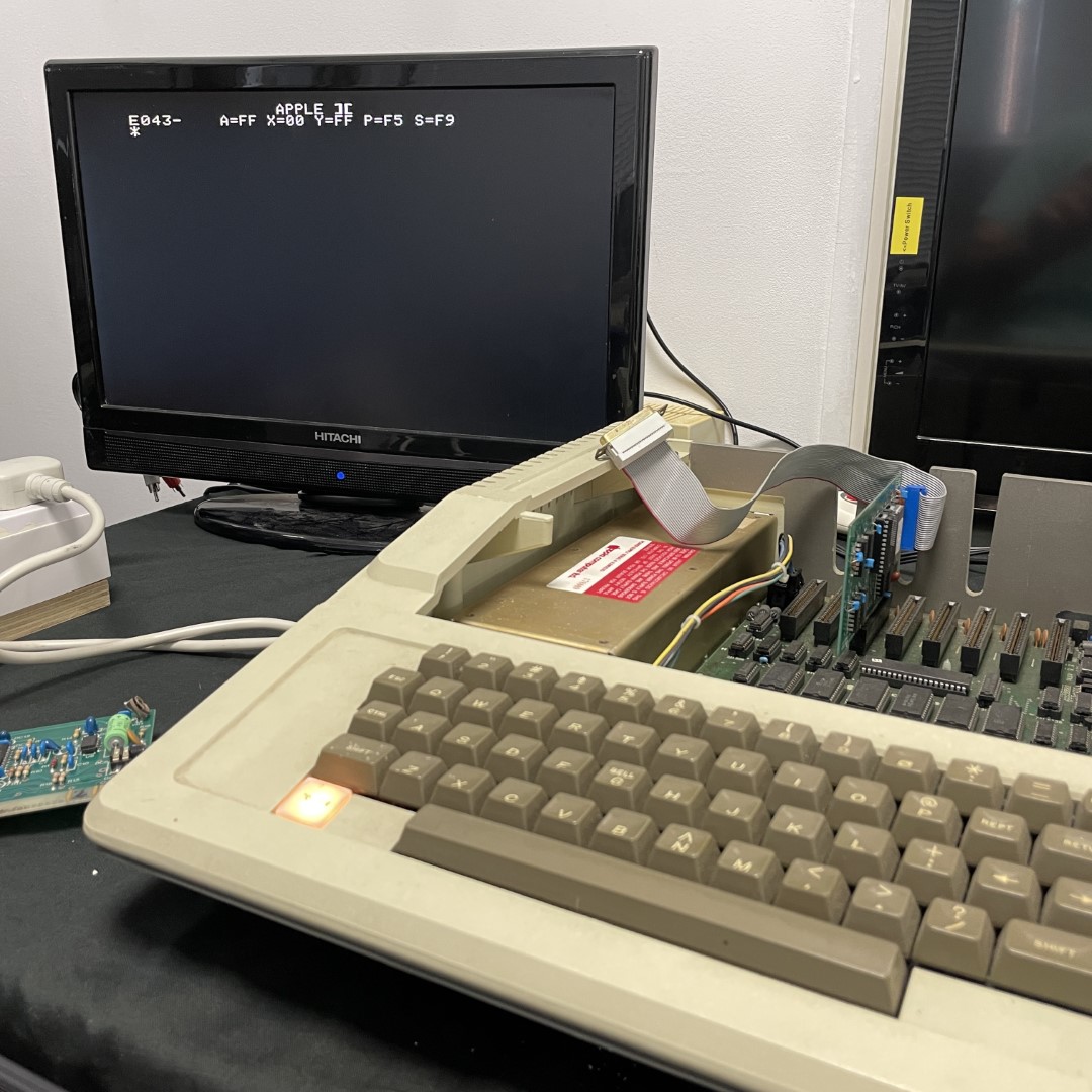
I'm trying to prepare an Apple // europlus for a small local no-profit museum so visitors can use it.
I am familiar with Apple //e and I am a bit lost here.
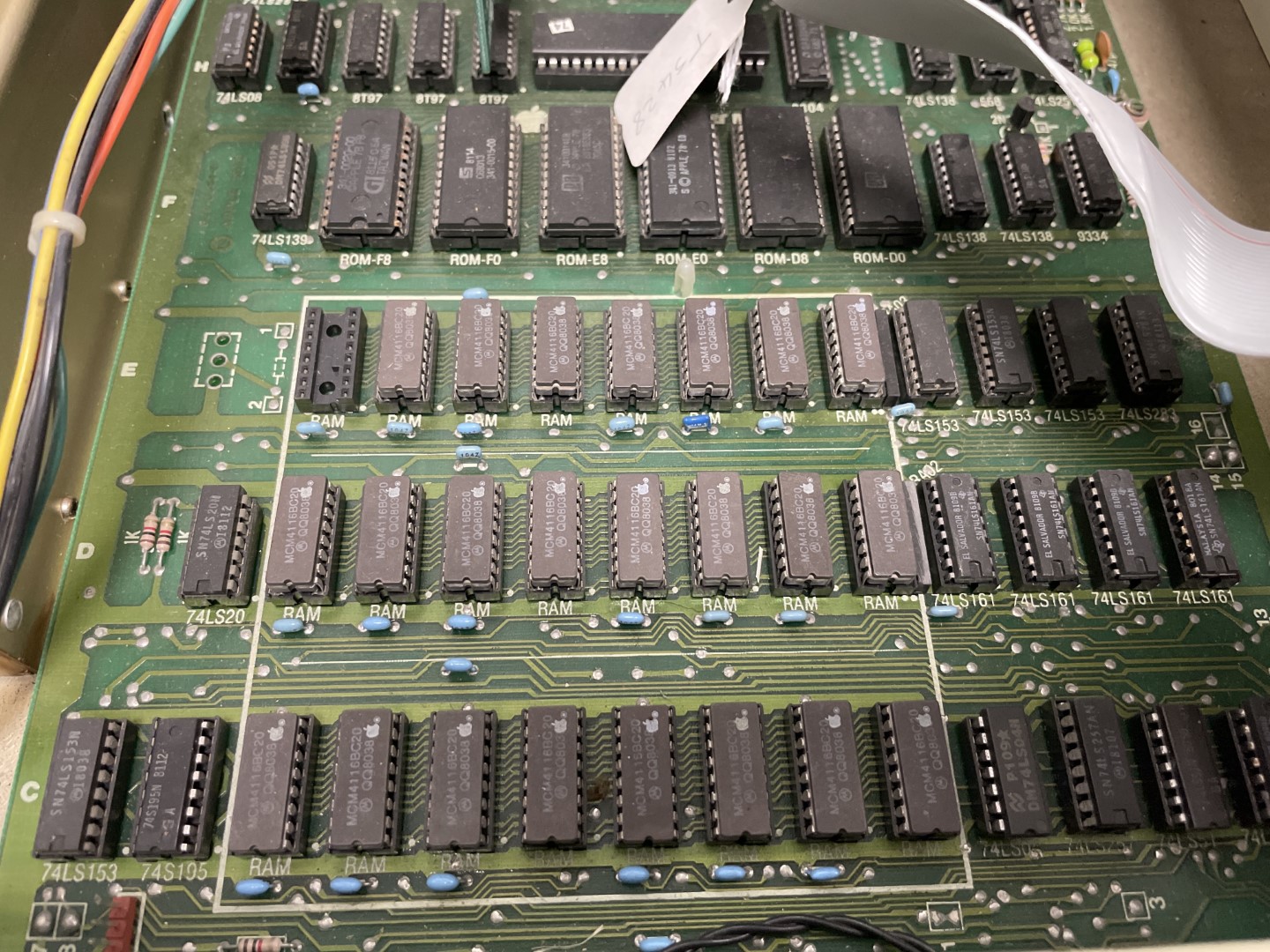
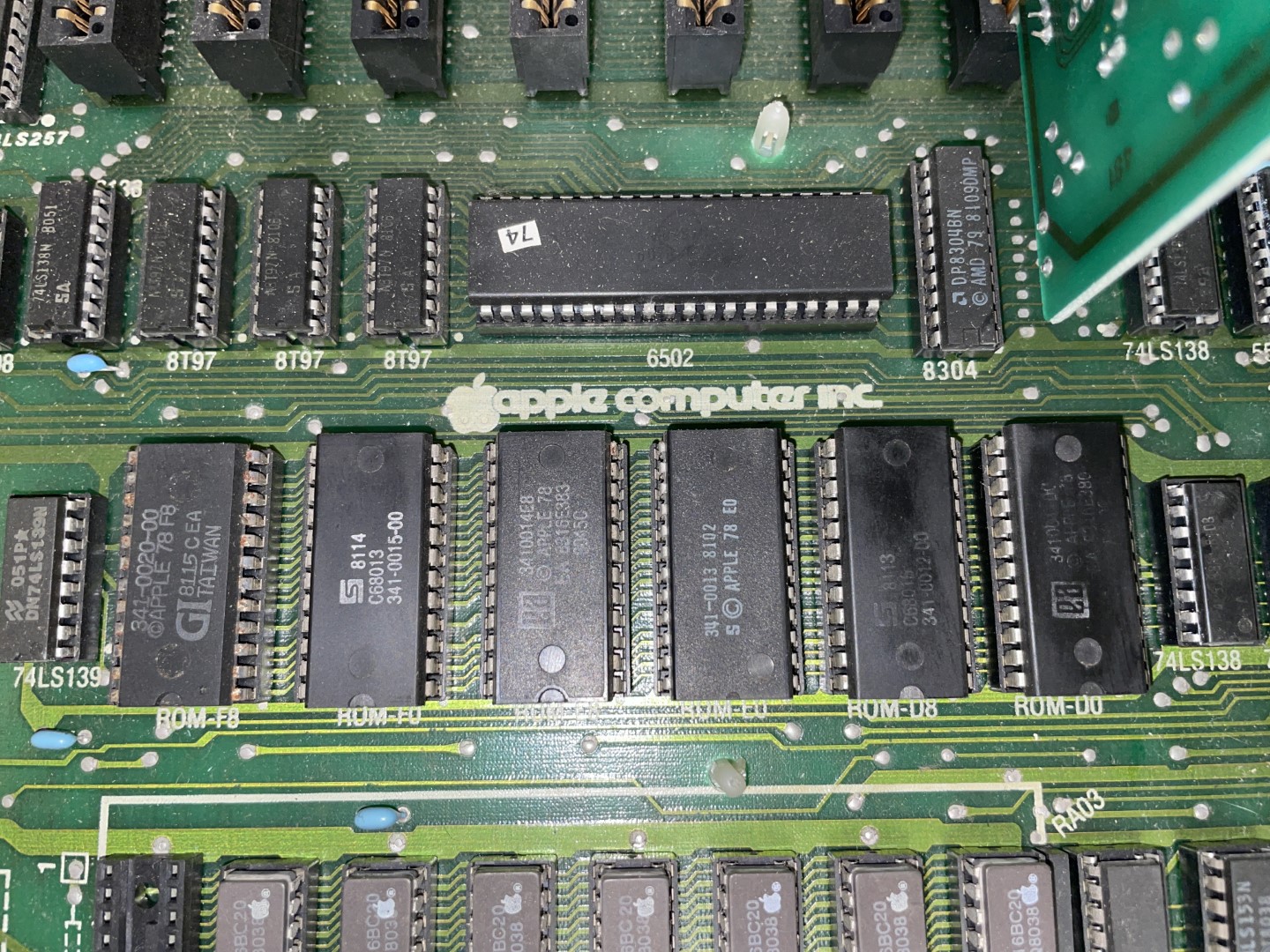
I understand the original Apple 2 did not auto-start so you had to type PR#6 to boot from floppy. However, ROM F8 is 341-0020-00 which I understand it should be the auto-boot one.
The other ROMS are
341-0015-00
341-0014-E8
341-0013
341-0012-00
(D0 is unreadable from the pic I have)
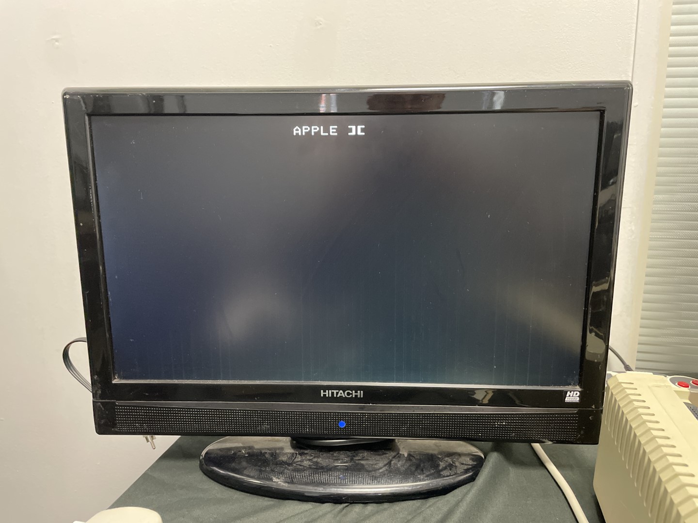
If I power up with a floppy controller in slot 6 and drive connected (which I don't know if it works) I have "Apple ][" displayed. If I hit "RESET" it takes me to Monitor. I tried CTRL-C, CTRL-B, CTRL-P and 6 and nothing works. The only key which works is RESET.
Without the floppy controller, the Apple beeps twice and drops me to monitor straight away.
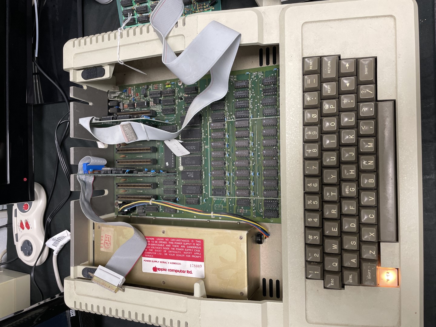
I see that 1 RAM chip at row E is missing and I understand that one might connect a language card there with a memory expansion. But I don't have a language card with this system.
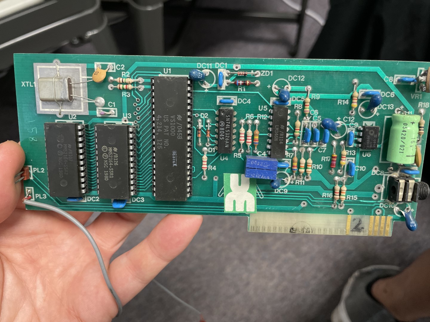
What I have is pictured below, plus the controller card. I haven't tested the board with the VS1000 on it as it has tantalum on the 12V line and I'd rather replace them before I use it.
I've re-seated and contact-cleaned all the RAM and ROM but nothing changes.
I don't know whether I am doing something wrong or maybe there is something wrong with the system.
Someone recommended I checked the ROM are still correct but I understand they cannot be read directly with my TL866II? A link online suggests I can just use an inverter to make them (2316B) compatible with something the TL866II can read (2716).
https://www.dmcmillan.co.uk/blog/testing-apple-ii-europlus-roms
Can someone help me? And is an inverter and some re-wiring really required to just read those ROMs with the TL866II? It feels weird.
Also, what would be the best way to replace those ROMs if needed? Is there a modern rewritable IC available? Does it have to be something which requires 21V programming?
Thanks for your help!
Tony
You need that one RAM chip. The machine will not work without it. When you put a language card, this chip is simply moved to the language card and you connect the ribbon cable in its socket.
If you don't have a RAM chip to put in the empty socket, you can still test the machine, but you have to remove the entire row. Then the computer will have only 32K of RAM instead of 48K, but it will boot.
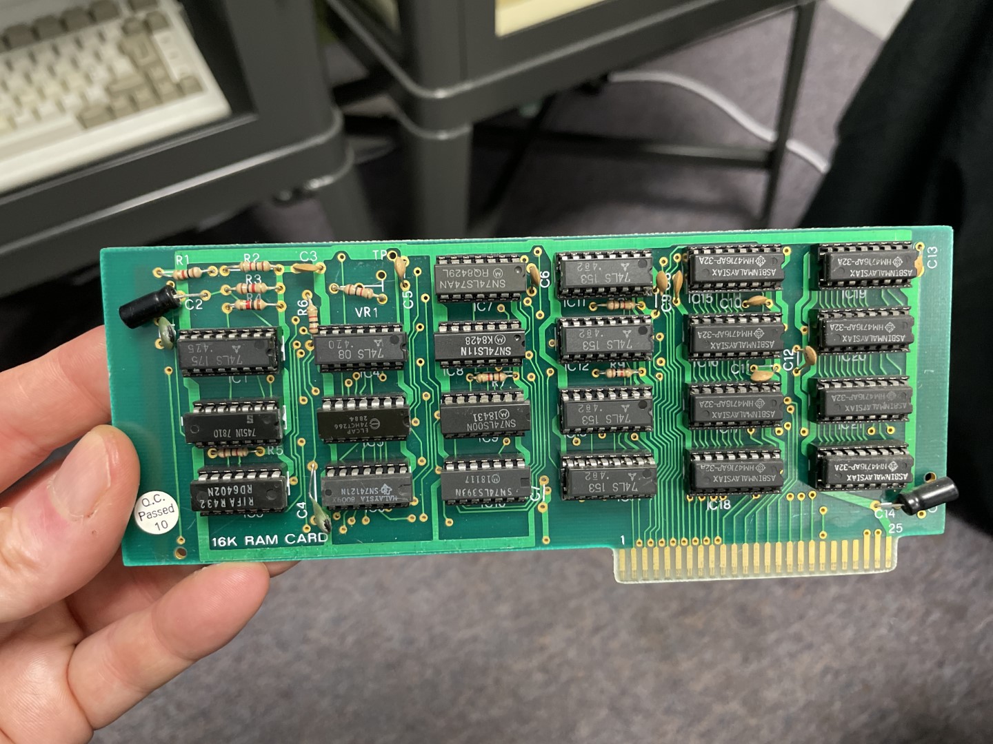
I can also see that you have a 16K RAM card. You can take one of the 8 identical RAM chips on the right side of the card and put it in the empty RAM socket on the motherboard. Then you should have the full 48K.
Thanks I suspected that. So I suppose there was a language card in this machine at some point. What does a language card do? I think we might have one somewehere.
However I did try that and it did not change the behaviour. I also tested the Floppy EMU and it wouldn't read so that removes the drive from the equation.
Can you - or someone - explain me what's the boot process of an Apple //? Would it be the same of an Apple //e if the auto-boot ROM is installed?
With no cards, you simply get a beep and a Basic prompt:
APPLE ][]■Try to find the missing Language card. It probably has the missing RAM chip.
The language card adds another 16KB of RAM to your system, so it has 64KB. And if it's an original Apple Language Card (not a clone) then it will also contain a newer version of the boot ROM with the "autostart" feature. Another reason to be looking for the missing card... :)
ah ok so there is something wrong with it then as I tested it without that row of RAM.
I will try to find the language ROM but we might not have it.
So what about testing/replacing the ROMs?
Having a missing RAM chip will not prevent the computer from working unless it's in the bottom row. You're missing chip will only disable the top row and leave you with a 32K machine.
As for the ROM, you might want to take a look at the ROMX .
I don't think the system is smart enough to realize it has only 32K complete if just one chip is missing unless I'm mistaken, which is possible.
I think, but I'd have to try it to verify that with no disk (boot device) installed it will go to Applesoft (or IntBASIC) but any memory access in the 3rd bank will be bad because one bit will be missing of every byte. Since the Apple II doesn't do any kind of memory checks to speak of it will work up to a point.
A missing chip in the 3rd row will cause DOS loading to fail unless the DOS is INITed for 32K or a MASTER.
I think the reason why you have to INIT for a particular size is that's the only way it knows where to try to load DOS. I'm not sure how a MASTER disk knows what the memory size is 32K or 48K (since DOS 3.x doesn't know how to load to a 16K language card without additional software). I suspect it does some kind of memory test in software loaded with the DOS boot process. Like trying to write bytes and read them back maybe? I don't remember if I knew at one time.
BASIC (both flavors) will do a memory check and set HIMEM accordingly. That's the only way the computer can detect how much memory it has. And a single bad/missing RAM chip will disable the entire row.
Gotcha.
However I did try removing the remaining 7 ICs and I still end up in Monitor. So I feel there is an issue here.
ROMX looks cool but really I don't need the extra features it brings. Is there a writable IC I could use to replace the ROMs, possibly with no or little modification? And what is the easiest way to check those ROMs with the TL866? I'm still puzzled that I need an inverter to read them, that would have been added in the IC library, no? I see the latest T48 programmer can use 25V to program, maybe upgrading my TL866II to the T48 would be a good option?
Also I tried connecting a drive to the system. It does change its behaviour a bit: no drive = double beep and monitor. Drive = it sits on "Apple ][" doing nothing until I hit RESET, then it lands on monitor.
I think start from a working set of RAM and confirming the ROMs are working should be my priority.
Unfortunately, if you replace the ROMs with EPROMs you are going to need adapter sockets (with inverters) for each chip. That will cosrt way more than the ROMX. You could also butcher the motherboard with your own EPROM modification but that's a bit more difficult.
Ok I need to understand this a bit more.
The original ICs are PROMs if I understand correctly? Particularly 2316B. My TL866II+ doesn't even read them so I sold it and ordered the T48.
Once I have it, I can at least check the ROMs against known good images.
If one ROM is defective, which IC can I use and will it require an adaptor regardless?
I see the RomX for the Apple II is $50 but I am in the UK so it makes things a bit more complicated.
Meanwhile I watched the last two videos of Adrian's digital basement and I see how the Apple II should boot, which is a step forward :)
|Thanks!
I stand corrected on that. It's been too long, I didn't remember all of that. I still think the part about DOS 3.3 boot failing on a 32K matchine if it was INITed on a 48K machine is true unless you used MASTER CREATE. Somehow I have a weird recollection of that being needed. Let me know if that is wrong also.
The TL866 won't read some of the weird old PROMs like a 2316 w/o an adapter. but that's true of a lot of them. I don't think that just to read a 2316 chip you need an adapter with an actual inverter though, the simplistic ones made with two sockets should probably work.
The T48 programmer looks interesting though. I will have to see if there is Linux support for it.
Not sure if it will read a 2316B either though. It seems to be touted as the next iteration of TL866. It looks like it may support some newer chips that the older versions don't. But FWIW, support for extremely old chips, the original TL866CS that I have will program a lot of 27xx chips that the newer TL866-II that I have won't. However, I've found the TL866-II seems to do a better job on some GALs. So I keep both.
Any IC that has a customer part number and copyright (e.g. "APPLE") is not a programmable anything. It was manufactured with data permanently wired at the fab as a Mask ROM.
These were sometimes called "mask *programmable" chips, but the term is confusing, because there is no way for a device programmer to write to them, and they never existed as a blank device.
You will not find bipolar PROMs used in any Apple II. They simply hold too few bits and are too expensive and laborious to program.
The T48 features Vpp up to 25V but you're right the 2316 is not on the list. LOL!
The T48 should be able to program those old 27XX which the TL866-CS used to be able to program.
Well, the out of pocket in the upgrade is £15 so I was just looking for an excuse to buy one.
I might email Xgecu, there is no need why the programmer shouldn't read the 2316. However, the 2316 datasheet says "pin compatible with 2716" and the 2716 is supported by the T48 *AND* the TL866II. So I am wondering if Xgecu just needs to fix the profile for the 2716 :)
Am I mistaken in thinking that the 2316 is not rewritable but the 2716 is - though with 25V Vpp - and which also needs to be UV erased? In that case, wouldn't I be able to replace a faulty 2316 with a 2716?
Reason I am asking is that the T48 supports the 2716 and I do have the UV light.
https://www.dmcmillan.co.uk/blog/testing-apple-ii-europlus-roms/2316%20Datasheet.pdf
Yes you can replace the 2316 with a 2716 EPROM. But you will need to use an adapter to re-map a couple of the pins. At the bare minimum you can do this with two sockets (see Sather, "Understanding the Apple II" page 6-15). Without an inverter however, there will be a conflict with the Apple ROM and Language Cards as well as any other board that uses the INH signal. So you should always use a proper adapter.
If you want to read a 2316 ROM in your programmer, ReActiveMicro does make an adapter.
Except for the DISK II controller board...
You are correct on this. The INIT command creates a "slave" diskette which needs at least as much memory as the system that created it. And won't use any excess memory if booted on a larger system.
Thank you. That chapter is what I was looking for to understand.
So Apple programmed those 2316 so that CS is active high - while 2716 are active low, hence the need for the inverter, even for the programmer to just read them.
Let's move in steps: first let me check those ROMs. For that I just need a inverter which I can borrow from the Apple itself. The T48 is on its way anyways - I sold my 866II in 2 hours and the T48 is not expensive so that's a "nice to have" anyways.
IF some ROMs are bad, I could either use RomX or I could make my own adaptor (which has an inverter on the PCB) and program some 2716, bearing in mind that not all 2716s are the same. Am I correct?
To test the RAM, which other device uses 4116 ICs? I can't use my Apple //e, can I? Or the Commodore 64. I remember there was an Arduino sketch to test those chips, maybe I can take a look.
Are there any Diagnostic ROMs I could use with the Apple II?
Thanks so far!
Just stay away from the TI 2716; it is not compatible. But a TI 2516 will work.
There are plenty of RAM testers like the Arduino one you mentioned but they don't always find every bad chip. Some may pass the test but still fail when used in the Apple II.
As for Diagnostic ROMs, there is an Apple Diagnostic Card but they're hard to find. Or the MultiROM card. But honestly, the ROMX includes a dead RAM Memory test, a full, burn-in quality RAM tester, as well as the Apple Diagnostics Program in one of its ROM banks. I know the shipping cost is an issue - maybe you can find a used one locally.
are those open source projects? I might think of putting one together for my toolbox.
If anyone want a Apple II Diagnostic Card I have a couple available for €55 plus €15 postage doesn't matter where you live. Alternatively you can just use the eBay link
https://www.ebay.com/itm/125980776422?mkcid=16&mkevt=1&mkrid=711-127632-2357-0&ssspo=BxWC1D9HRTK&sssrc=4429486&ssuid=BxWC1D9HRTK&var=&widget_ver=artemis&media=COPY
There's also the original Centronics Interface card and their original Parallel Printer card. (These were two distinct cards.)
Plus Apple's original serial interface card, the version before the "super" serial card.
And don't forget Apple's 1982 combo Printer/Centronics card, which employed an LS472 to double the quantity of bipolar PROM in order to include the firmware from both the Centronics Interface and Parallel Printer cards.
(In short, there are a lot of Apple branded cards that use bipolar PROMs. A lot of third-party printer cards do too.)
Well the RomX is a tad expensive to ship so I'll think of alternatives :)
romx.JPG
You can also boot without any of the ROM chips if you have a MultiROM card. I have one for sale that I don't need any more. I bought it when I also thought that something is wrong with my ROMs. They turned out to be fine and I wouldn’t be surprised if yours are fine too. PM me if you are interested. Shipping it from Bulgaria to the UK will not be more than $7.
MultiROM.png
MultiROM card.JPG
Hi,
I've built myself a "ROM replacement" adaptor.
https://oshwlab.com/kris.garrein/apple-ii-rom-replacement-board_copy
I wanted to test the ROM on my Apple //e and if not mistaken this adaptor won't work there so I wanted to whip one together just to make sure the ROM is working - so I know it should work on the unhappy Apple II.
I cannot find a schematic of the adaptor needed, can someone point me to the right direction please?
Also, is there a pre-made ROM for a 27C256? I can try to append together the ones I find online as directed in the manual but I suppose someone must have done this before!
I'll also test Adrian's digital basement ROM which seems very good!
Finally, I have several 27C512. Can I use them leaving half of the ROM empty?
Thanks!
Ok so I managed to replace the ROM with the ROM Replacement and it works - only from one of the banks though but maybe I made a mistake concatenating things together.
To start the drive I have to type PR#6 though, which is weird as I used the autostart ROM of course.
My next questions are:
- what is the difference between Integer and Applesoft basic?
- How do I run "inspector" or "Watson" which I put on the ROM?
- The latest diagnostic ROM from Adrian's digital basement seem to say the RAM is correct but it fails to display the final table with the result. Instead, it shows a screen of "@". Could that be because it's a PAL version with UK keyboard - UK Rom I guess? Or does it indicate a fault somwehere?
- What is a good diagnostic software I can use with an Apple II europlus?
I've managed to run XPS but didn't realise it was the Apple //e version so obviously that fails memory test. I ran Frogger and that ran fine but I'm not sure about colours as m capture device was having issues displaying the signal altogether.
Thank you!
To run Inspector or Watson, just jump to the base address of the ROM socket it's in. If you have both Inspector and Waton installed, it will start as Watson (the sector viewer/editor). I regularly use Watson, but I don't have any experience with the Inspector.
So if you installed your Watson ROM in the
D0socket, run Watson with the commandD000Gin the Monitor.Ah I see.
The ROM is a single large one and it's made like this:
"The EPROM is structured as follows: first it contains 4K empty data, followed by the 4x INTEGER ROMs, 1x Inspector ROM and 1x Watson ROM. Then 4K empty space again, followed by the 6x Applesoft ROMs in order D0, D8, E0, E8, F0 and F8"
Can someone explain me how to match the numbers I get using an Hex converter to the memory map please?
If I use Windows calculator, 2K are 800. So I have
0K-2K - 000 - 800
2K - 4K - 801 - 1000
4K - 6K - 1001 - 1800
etc.
How does work that with a memory map I find here for example? http://apple2.guidero.us/doku.php/mg_notes/general/mem_map
Maybe I can answer myself: D000 = 52KB. So that 2K ROM is mapped to that location The position in the ROM doesn't mean anything, the ROM will then be mapped into RAM at location D000, is that correct?
The web page doesn't give a schematic diagram, but it's straightforward to follow the circuit of the ROM Replacement Board from the PCB.
The circuit interfaces a 27256 by lifting three address lines (A11, A12, A13) from the motherboard, and controlling A14 with the bank-selection jumper.
So, here's how the contents of the EPROM appear to be mapped to the motherboard sockets D0, D8, E0, E8, F0, F8.
0000-07FF0800-0FFF1000-17FFD000-D7FFD01800-1FFFD800-DFFFD82000-27FFE000-E7FFE02800-2FFFE800-EFFFE83000-37FFF000-F7FFF0F800-FFFFF84000-47FF4800-4FFF5000-57FFD05800-5FFFD86000-67FFE000-E7FFE0E87000-77FFF000-F7FFF07800-7FFFF800-FFFFF8The bank-selection jumper chooses which set of ROMs will be present.
When the bank-selection jumper is placed in the first position, then the EPROM adapter behaves as though the sockets contain ROMs for Watson, The Inspector, Integer BASIC, and the original Apple Monitor. When you switch-on the computer, it will start with a Monitor prompt. To start Integer BASIC, press
CTRL-Band press return. To run Watson, typeD000Gand press return. (The Applesoft ROMs and Autostart Monitor are not available in this configuration.)When the bank-selection jumper is placed in the second position, then the EPROM adapter behaves as though the sockets contain ROMs for Applesoft BASIC and the Autostart Monitor. When you switch-on the computer, it will automatically start BASIC or boot a disk drive if one is installed. (Watson, Integer BASIC, and the original Monitor are not available in this configuration.)
Thank you for taking the time to write that for me, appreciated!
My issue was with a 512 ROM IC and someone has pointed me to the right direction (indeed the 512 comes with an extra address line which ended up being shorted to 5V on that socket hence my configuration wouldn't work).
Rather than fiddling with the 512 I've sourced a 256 to test.
I got to the point of "where to put what" (*) but you explained the "why" which I appreciate.
One thing I am not sure is: the manual mentions "Integer Basic, Inspector, Watson" but you are listing "Watson, Inspector, Integer Basic". I suppose your table is correct as F8 is the monitor for both configurations.
I'll make another set with this order.
One basic question I still haven't found an answer to is: what is the difference between Applesoft and Integer Basic? Also, Watson is a diagnostic software, right? But what is the inspector?
Thanks so far, I'll share the final ROMs once I have confirmed they work.
Integer BASIC was the first ROM BASIC for the Apple ][, adapted by Woz from a prior BASIC he wrote for the Apple I. By its name, you can see how it is special: the only numbers it supports are integers from -32768 to 32767.
Applesoft BASIC was based on Microsoft's BASIC and supports floating-point numbers (9 decimal digits with a two-digit exponent). There are a few other syntax differences.
The principal difference between an original Apple II and an Apple II+ (plus) is the former came with Integer BASIC ROMs and the original Monitor ROM; the latter came with Applesoft BASIC ROMs and the Autostart Monitor ROM. The hardware of a II and a II+ are identical.
Either a II or a II+ could run the "other" version of BASIC by installing a Firmware Card or a Language Card in Slot 0. The Firmware Card has sockets for the alternate BASIC in ROMs, and a switch to select whether the card's ROMs or the motherboard ROMs are used. A Language Card has 16KB of RAM into which the alternate BASIC can be loaded by a "Master" boot floppy. Once booted from DOS, the "INT" and "FP" commands switch between the two versions of BASIC.
The two BASICs used different prompts: the Integer BASIC prompt is a greater-than sign, ">"
The Applesoft BASIC has a right-bracket sign, "]"
Some software requires either Integer or Applesoft BASIC, so having a Firmware or Language Card was important, besides the possibility of using the additional 16KB of RAM (on the Language Card) for machine-code programs.
The Apple IIe and GS don't have a Slot 0, so can't use either of these cards. Their AUX slots are used for different memory expansion options (such as the 80 column-64KB card for the IIe).
Actually it's from -32767 to +32767. Integer Basic doesn't support -32768.
Thanks Robespierre, very comprehensive explanation!
Actually you can use an INTBASIC ROM Card in a //e if you do a little mod. Because of where the switch is on the board it won't fit into a //e so you have to unsolder the swittch and put it on some wire you can feed out the back. The ROM card won't automatically be enabled like it is on a ][+ in slot 0, but you can put it into another slot and then flip the switch and hit CTRL-RESET and get into INTBASIC. It will also work when modified like this in slots other than those where the switch would normally like up in a ][+. I used to use a ROM Card like that for copy protection cracking.
Forgive me for nit-picking, but some of these details are worth straightening out because some useful features are being clouded in confusion:
FPandINTcommands if the Firmware Card is installed in a different slot -- you'll just need to usePOKEs or Monitor commands to activate the Firmware Card. (See below for addresses.)Here are the IO addresses and POKE commands for activating the Apple Firmware Card. It's best to use the Monitor or machine-code to switch ROM banks, as the POKE commands will crash if you activate a ROM configuration that doesn't include the same BASIC interpreter.
C080- ROM card onC081- ROM card offC082- ROM on, second bankPOKE 49280,0
POKE 49281,0
POKE 49282,0
C0B0- ROM card onC0B1- ROM card offC0B2- ROM on, second bankPOKE 49328,0
POKE 49329,0
POKE 49330,0
IMG_1203.JPG
IMG_1205.JPG
S.Elliot, do you have the schematic or photo handy for the Apple ROM Card mod?
Also, what is the difference with Watson 4.0 and Watson 6.0? (I thought there was only one release of Watson)
It will barely fit, but it more or less requires having the top cover off and even then is often difficult to flip the switch in a //e unless you relocate the switch on some wire like I did for mine. It's a simple mod and although possibly not technically necessary for a //e, it is extremely convenient to have the switch outside the case.
I don't have a schematic. Any paper notes of the modification would have been discarded long ago.
But here's a quick summary and photo of it:
IMG_1211.JPG
capture354.png
Thank you S.Elliot! The mod is now added to my archive.
Maybe I will create a complete schematic for the mod in the near future based upon the pic.
Do you by chance have a source for the 2 Watson verions? (4 & 6) Thank you in advance!
An update. I have sourced a 256 ROM and programmed as you suggested. I think it works. I have integer with the > and I can run code. On the other bank I get Applesoft and I can run code.
HOWEVER.
It does not autostart. Unless I misunderstand that? With "autostart" I expect to flip the power switch and the Apple immediately starts booting from the disk.
At present, it sits on "Apple ][". If I press RESET I end up to Basic prompt ]
If I type PR#6, it boots from the floppy and runs programs.
With no controller card in it, when I power up I immediately end up on Basic prompt ]
What am I missing? I am using these ROMs:
http://mirrors.apple2.org.za/Apple%20II%20Documentation%20Project/Computers/Apple%20II/Apple%20II%20plus/ROM%20Images/
Thanks so far!
The F8 Monitor ROM in an original Apple II does not autostart; the F8 Autostart ROM was part of the package on an Apple II+.
The Language Card also has a socket for a substitute F8 Autostart ROM that overrides the motherboard F8 socket.
But I chose the "Autostart" ROM, which was also what was installed.
The ROM I programmed in F8 is called "Apple II+ - 341-0020 - Applesoft BASIC Autostart Monitor F800 - 2716"
Taken together, those three behaviors might indicate a faulty 74LS138 at position H12 on the motherboard. That's the 3-to-8 Line Decoder that sends IOSEL to each slot, which activates the bootstrap ROMs for each card. If the 74LS138 has developed a fault that causes it to erroneously activate IOSEL on slot 6 when the Autostart ROM searches for a boot ROM in slot 7, then it would erroneously try to boot from slot 7. Since slot 7 doesn't actually contain a disk controller, it would get stuck waiting at the Apple ][ message until you press RESET.
But that's just a guess, a shot in the dark.
Because the disk controller can operate in any slot between 1 and 7, you can test it in another slot and make note of how it behaves. For example, with the controller installed in slot 7 does Autostart boot it automatically? With the controller installed in slot 7, can you boot it manually with PR#7?
Ok so the first breakthrough for me is: it's not supposed to behave like this! Thanks for that!
I'll have to study the schematics and the service manual, thanks for your input.
I have tried and you were spot on! :) Drive spun on slot 7. I swapped H12 and it works now - it only boots from slot 6 but I believe some disks were hardcoded to look for slot 6 so I think that's fine (*yes, other disks boot fine from other slots). The drive does automatically spin with the controller in any slot now.
I'm now curious to see what the fault is using an oscilloscope. I understand the ROM will look for a sign of the disk drive controller in all the slots. So, without a disk controller, am I expecting to see the I/O Select lines to become low one by one from 7 to 1? And with a controller in slot 6, I'd expect 7 to be come low, then 6 and then it would stop there every time the drive is being accessed.
So if I understand correctly, pin 9 of that 138 is probably stuck low. That way slot 6 is always selected. So at boot up the ROM checks for the drive in slot 7 - but the IC is selecting 6. The ROM finds the controller and thinks it's in slot 7, hence it tries to boot the drive in slot 7, which is not there.
My question is: it looks like there are two paths to reach a slot: the I/O select line but the ROM can also access it independently. Otherwise with a stuck low pin 9, slot 6 would be used all the time regardless. The behaviour I'd expect in that case is that "only slot 6 works".
I've looked through a few manuals, the picture is getting clearer and wondering if you could help me understanding better! :)
But thanks so much so far!
Ooo, you're a quick study!
Slow down, though...we need to go back one step:
Almost, but not quite. Yes, pin 9 must be going low at the wrong times...but it can't be stuck low. The Disk II controller connects IOSEL directly to its 6309 ROM; if pin 9 was stuck low then IOSEL would continually drive the controller's ROM onto the data bus, causing a conflict with the motherboard's RAM and ROM. But the motherboard's RAM and ROM are working fine, so we can infer that IOSEL is not being asserted...and therefore pin 9 is not always low.
Disk II controller ROM on data bus.png
So, here are a few alternative guesses how the LS138 might malfunctioning:
Luckily there's a simple test to distinguish among all of those cases: install the controller in any slot, then use Monitor commands to list the ROM at each slot's assigned address. Slot 7 is assigned ROM address
$C700-C7FF, while slot 6 is assigned$C600-C6FF, slot 5 is assigned$C500-C5FF, etc. When the controller is installed in slot 7, you should see a listing of the boot firmware (pictured below) when you enter the commandC700Lin the Monitor. But it will just list random byts if you attempt to list the address for some other slot; eg: if you enter the commandC500Lit shouldn't match the listing below, and it will probably give different results each time.Disk II firmware listing.png
Bonus Trivia: the 6309 ROM is equivalent to 74LS471. Some [rare] Disk II controllers have Texas Instruments ROM chips marked "74LS471" at locations B3 and D3. Does yours? (Other part numbers are more typical.)
This is very cool, thanks for that.
I did check with the scope before you posted and noticed that slots 7,6,5,4 have pulsing happening all the time - slots 3-2-1-0 show pulsing but at a slower pace.
Replacing the 138 brings things back as expected: there is ONE pulse on each slot with no controller starting from slot 7 until a controller is found - then no more pulses on remaining slots. The slot with the controller then shows activity on the Select line of course but the others are quiet.
I checked via monitor and indeed with the controller installed in say slot 6, I can see the controller ROM on slot 7,6,5,4 simultaneously but the controller ROM does not show when I check on 3,2,1 and 0. So it's as you suggested: the routine is scanning the slots, the ROM appears on slot 7 and the software tries to boot from slot 7.
How does that work with the binary of the 3 inputs?
I've also noticed that if I place the controller on slots 0,1,2 or 3, (this is with the faulty 138) when I power up I land on BASIC but the computer is inoperative, keyboard doesn't work and/or I get two (non-functional) prompts - suggesting maybe the controller ROM is conflicting on the BUS?
There is still something I am not sure I understand.
Let's assume slots 4,5,6 and 7 are being "selected" simultaneously - this is what the monitor seems to suggest, right? So the controller appears simultaneously on all those slots. Shouldn't a SINGLE controller card plugged in any of those slots work with no issues then? In other words, let's say the controller is in slot 6. The fault makes it appear in 4-5-6 and 7 at the same time. The computer starts scanning from slot 7 and since it can see the controller there, it assumes it's in slot 7. Then the computer tries to boot from slot 7. When it selects slot 7, it's actually selecting 4-5-6 and 7 at the same time. But if only ONE card is in one of those slots, I would expect that not to make any difference and I would expect the drive to boot ok?
But thanks so far, it's amazing to diagnose issues at this level rather than replacing the faulty part and "it works" :)
Ooo, that means none of my guesses were entirely right. And I totally missed a clue!
So the motherboard's built-in IO occupies addresses
$C000-C0FF. That's why slot 0 doesn't support devices with ROM -- those addresses are taken by the motherboard IO. So the 138'sZ0output (pin 15) is used to activate on-board IO, instead of being the IO SELECT for slot 0.Here's the schematic of the decoding circuitry for IO SELECT and DEVICE SELECT, with labels for the address wires. Z0 is used for all motherboard IO and for the DEVICE SELECT for all slots. Z1, Z2, and Z3 are used to activate device ROMs in slot 1, slot 2, and slot 3. Your faulty LS138 at H12 always activates all four outputs Z0, Z1, Z2, Z3 at the same time -- so the ROM for any card in slot 1, slot 2, or slot 3 would cause a conflict with all motherboard IO and all slot IO!
So that's why your computer wouldn't work when you installed the Disk Controller in slots 0-3.
IO SELECT decode stage.png
Let's follow the signals to the ON BOARD I/O DECODE stage...
Ordinarily, the motherboard would only activate this decoding if you attempted to access motherboard IO and soft-switches. But your faulty LS138 will also activate these circuits if you try to read the ROMs for devices in slot 1, slot 2, or slot 3. Conversely, any device in slot 1, slot 2, or slot 3 will assert its ROM onto the data bus if you try to access any motherboard IO ports.
IO onboard decode stage.png
So, here's a weird experiment...
With the faulty LS138 installed, and slots 0-3 empty, try using the Monitor command
C100.C13Fto print the first 64 bytes of the ROM in slot 1. I'm guessing it will behave like this:0D, the hexadecimal value you generated by pressing the RETURN key.IO with faulty LS138.png
(Note: this picture is just a mockup, my best-guess at how it will behave)
I need to digest the explanation a bit - but I tried the last command and I get the below, plus some very faint noise on the speaker but not beeps. (sorry, capture device was unhappy)
appleII screenshot.png
One more question about the Apple II Europlus.
I understand this machine is NTSC so it was released for the European market when it comes to input voltage but Apple did not change the video output so a monochrome picture is to be expected with it.
However, shouldn't colours appear on a capture device NTSC capable - or an NTSC capable monitor?
Pages