16k memory ram card, had a capacitor smoke. I had installed a new Apple II VGA card I had just assembled and was testing the machine. I had considered leaving the top of the case open while I tested my newly built card but I didn't since I was running out of desk room.
I out the cover in and powered the machine on and my VGA card seemed to be working perfectly. Although it didn't seem to work in 80 columns on my II+ but I am not sure of that is normal or not. I turned the machine off after about 10mins.
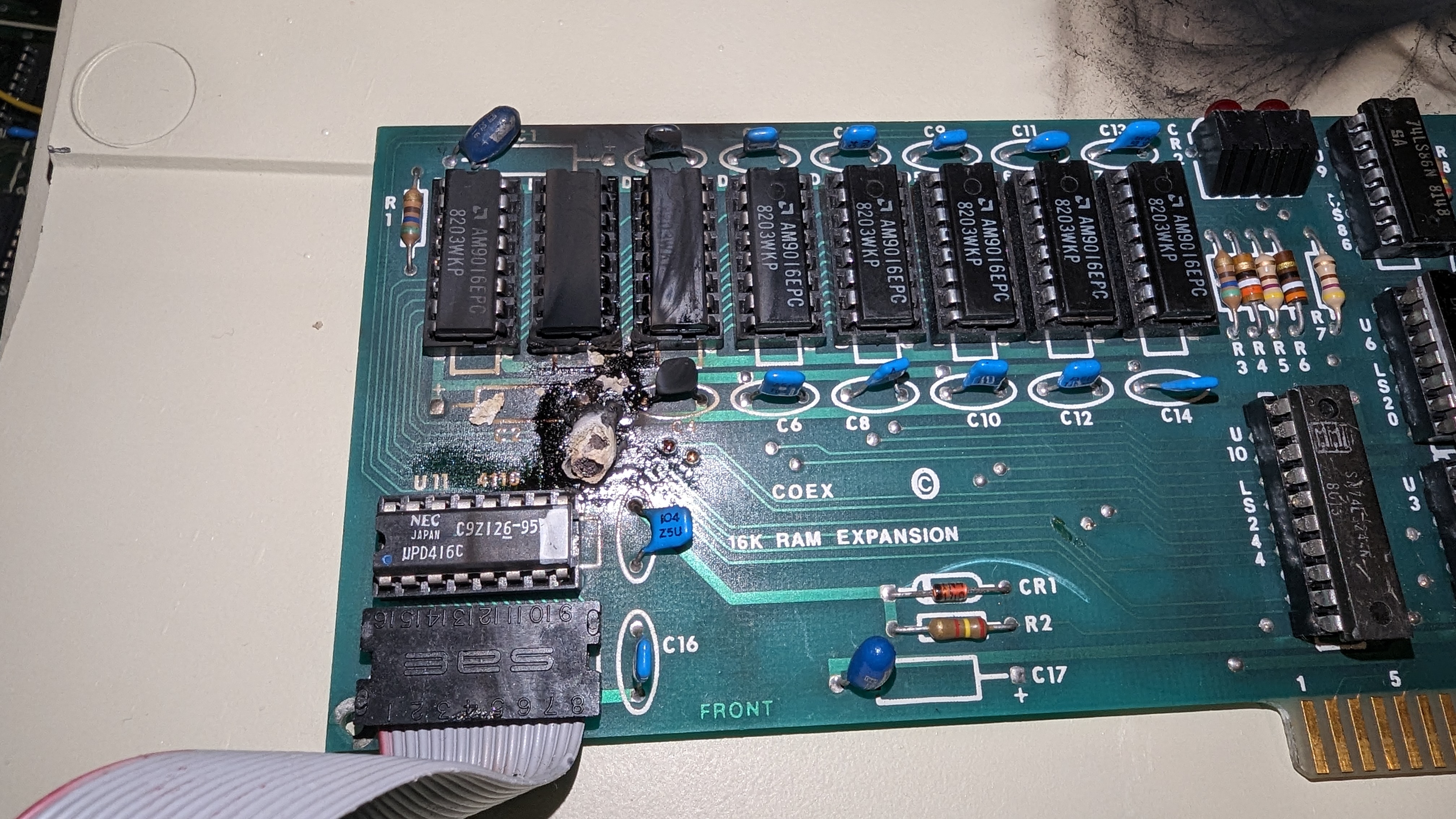
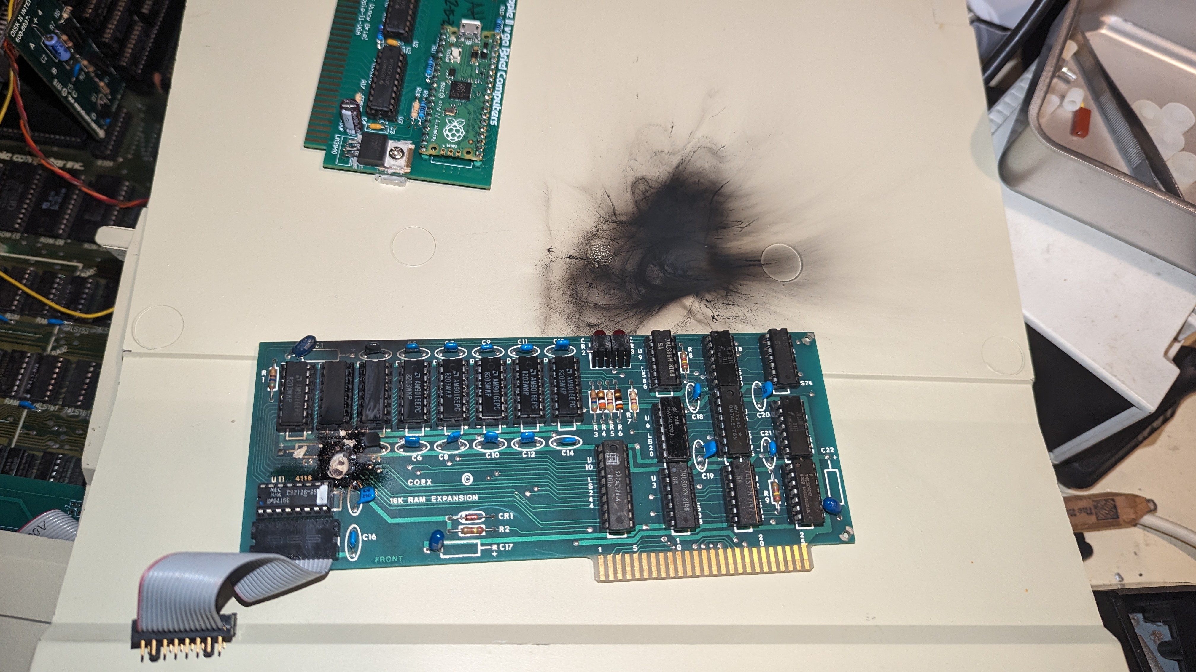
Today I just popped off the top case and noticed a big smoke stain on the top. I hunted around for what blew up and it was C2 on my COEX ram expansion card.
Are these just tantalums being tantalums and blowing up, or is it likely my VGA card was maybe shorted or something? The timing just seems too close.
I guess I'll start by beep testing the power pins on the memory card and my VGA card to see if any power rails are shorted.
40 year old capacitors going bad... not a big surprise. If your VGA card is working it probably has nothing to do with it.
The Apple II Documentation Project shows a picture for the COEX 16K card.
The capacitor at C2 is an axial aluminum electrolytic. I can't quite read the ratings, something about 85°C and maybe 16VDC?
When capacitors like this blow up, they eject a long length of spooled up aluminum foil. Check to make sure you have cleaned all of it up because it can short circuit whatever it falls across.
Vishay and Kemet still make axials. Nichicon still lists one axial type.
http://mirrors.apple2.org.za/Apple%20II%20Documentation%20Project/Interface%20Cards/Language%20Cards/COEX%2016k/Photos/COEX%2016k%20-%20Front.JPG
The photos above show that C1+C22 are also tantalum capacitors on this board - whereas the other photo shows C1+C2+C22 with electrolytic caps. So this board has footprints for both options - some boards used electrolytic and some were produced with tantalums. And this board indeed used tantalums. Advantage is, you could now also use radial electrolytics caps, since this boards has both footprint options (radial+axial).
The photo looks pretty dramatic though. That tantalum certainly decided to quit and leave a long lasting impression... Did it burn through the traces on the PCB or is that on the photo just smudge on top of the PCB?
It was definitely a tantalum cap. It is very common for old ones to internally short and then explode in a similar fashion. Electrolytic caps don't make this type of a mess and you can tell from the picture that the + side of the axial footprint was never soldered.
I would get rid of the tantalum cap just above it too! Considering that they are probably from the same manufacturer, it's not a question of if, but when.
The board is pretty badly burned in that area.
It may have scorched through the traces but not sure. If I know where they went I could use my multimeter and test.
Ive had a few tantalums on IBM 5150 boards blow up before, but nothing like this. Also the IBM PSU shuts down when there are shorts, not sure if the apple one does.
The other linked COEX card has some values of 20uf but the C2 capacitor looks larger and possibly a different value than the others.
Ive searched for images of this card and found some have electrolitic caps there, axial caps, and tantalums. Seems they used all sort of different types, just don't know what value goes in C2.
That's a pretty cool explosion.
Those capacitors are meant to smooth out the power supply and filter noise. The values are not that important. 22 uF is a good common value, easy to find. Make sure you get 16V or 20V rated ones.
You can replace both the tantalums with elecrolytics if you want.
I'll replace them and hope the traces still work.
Funny thing is, I had no idea it even blew up until I opened the lid the next day. Didn't see or smell smoke and didn't hear anything.
In post #1, 'HiSir' wrote:
" Are these just tantalums being tantalums and blowing up, or is it likely my VGA card was maybe shorted or something? The timing just seems too close. "
Uncle Bernie comments / warns:
Solid tantalum capacitor are notorious for developing grain boundary defects with age. The process can be accelerated by briefly reverse biasing them. Which, due to some poorly designed power supplies, actually can happen when the power is turned off (I don't think Apple products ever had this problem, but who knows what can happen in 40 year old power supply circuits with 'walking wounded' or dead components four times past their design life).
Once a grain boundary is damaged, the leakage current of the properly biased / polarized solid tantalum capacitor is increased over the undamaged example. The damaged grain boundary/ies locally overheat due to the increased leakage current and this increases the damage and the leakage current in a runaway process, until the whole solid tantalum pill glows bright white (1400 deg C, or 2500 deg F) and at this temperature, all organic compounds get split to provide fuel for a fire. This is why such a tantalum pill glowing bright white can even ignite the FR-4 PCB board material despite it is advertised as being "inflammable".
For mainframe computers, this was a huge safety and reliability issue. I once worked in this field so I know everything about the dangers of these tantalums first hand. A (partial) solution was to put a tiny fuse into the tantalum capacitors, which would open before the current would get high enough to ingnite anything. The reverse polarity risk was solved by giving them three legs so it was irrelevant if they were put in turned 180 degrees. But these were special types for mainframe computer manufacturers and I don't think they ever became popular in the general electronics industry, or, - yuck - the so-called 'consumer' electronics industry, where the cheapest and most ridicolously cr@ppy components must be used to stay price competitive.
The Apple II power supply is not able to provide enough current in the +5V rail to get the tantalum capacitor to bright white glow and to incinerate everything. But as we can see in the photos of this thread, the damage still can be pretty bad.
Take my expert advice: every solid tantalum capacitor is a ticking time bomb which can go off at any moment, without prior warning, and the risk increases with age. The best course of action is to desolder all of them as a preventive measure and to put in one of the non-polarized high capacitance ceramic capacitors (most of which are SMD). But be very careful with those, too, they do not like mechanical stress, especially during hand soldering. I use a regulated heat gun in a holder aimed at the PCB site to keep the temperature to about 150 deg C while soldering in these high capacity SMD capacitors, and then remove the heat gun, allowing everything to cool down at the same time. If you don't do that, and hand solder one end of the SMD first, and then the other one, you create thermal-mechanical stress which might already produce micro cracks in the ceramic material. These cracks then might grow with every thermal cycle (turn on/ turn off) until the capacitor fails. But these ceramic capacitors typically fail as open circuits, or reduced capacitance, and not as short circuits.
If you do more SMD work, get at least a temperature controlled heated plate on which you can put the PCB and heat it uniformly. And then you can get more professional and use the SMD glue to fix the SMDs in place and use the SMD solder paste. You can do the reflow soldering with a temperature regulated heat gun. If you have invested in such a SMD repair station and follow the industry standard repair procedures, you can make high reliability repairs of SMD based electronics. But for the occasional use by hobbyists, this is too expensive and dead capital. I use SMD occasionally and do everything without any special SMD tools. But I know which SMD components are easily damaged and which are robust. With experience, you also can do this SMD work without special tools, and avoid the dreaded cracks in SMD ceramic capacitors (a telltale sign seen under magnification is a crack between the ceramic material and the solder contact end of the SMD, this means to worked too hot, too long, or too clumsy). Note that not all SMD components are so delicate, most of them are quite robust. But any high capacity ceramic SMD capacitor (above 100nF) may be delicate and need the heat gun trick explained above, to avoid internal cracks. Hint: when using high capacity ceramic SMD capacitors, say, above 100nF, always buy the highest voltage ones which fit in the footprint. These use thicker ceramic layers and are more robust.
- Uncle Bernie
I should get some SMD kit sometime soon. Thanks Uncle Bernie.
For now, I hope this works. Recapped the big tantalums.
PXL_20231217_183812841.jpg
Seems to be working fine now after the recap, even with the VGA card in.
Thanks all.
Excellent news!
Thank you.
We always appreciate a posted resolution to the issue at hand.