
I wanted a reliable and easy to use adapter for the Apple /// system ROM ("B9 ROM"). Something to plug standard EPROMs & EEPROMs. I want to make a few ROM extensions - making use of the second ROM bank, which was orignally unused. Apple only installed 4KB ROMs, though 8KB were supported (split into two banks) - but the unused second bank just returned random data. Maybe Apple intended this to be used for future updates. But we all know that never happened...
The tricky bit about the adapter is the really, really tight space inside the Apple /// chassis: the infamous heavy and thick Apple /// aluminum cast chassis, allegedly made by a company normally producing motor blocks. And if you ever seen or lifted one of these, you know it's probably true. To make matters worse, the "B9 ROM" sits in one of the tightest spots: right below the angled keyboard - and even below an embossed production seal (lot number/date stamp), which protrudes into the chassis by another 2mm or so.
My first attempt for the adapter failed by a few millimeters. But version 2 now works great.
It moves the EPROM all the way towards the rear - and rotates it by 90 degrees. It sits right between the CPU and one of the logic PROMs. The PCB sits flush on top of another IC (a standard LS TTL in positon C9). But these barely dissipate heat, so it's not a major concerning with cooling.
Everything installed, it looks like this:
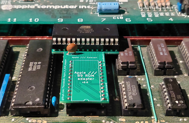
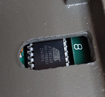
At the top it has about 4mm clearance to the chassis now. I used an 8KB EEPROM (28c64), but the clearance is enough to also fit EPROMs (27c64) which are usually a bit higher.
Here's what it looks from above, inside the chassis, with the keyboard removed:
Don't use normal pin headers to make the connection to the B9 ROM socket. This would damage the socket. I used extra thin, rounded pin headers. My github shows these in detail.
My PCB design can be found here:
https://github.com/ThorstenBr/Apple_III_ROM_Adapter
Custom ROMs
I also started making some custom ROMs. I had already made one for the DAN][ Controller, so the Apple /// can "autostart" with the DAN][ just as we know it from the Apple ][. The Apple /// stock ROM couldn't do that (no "autostart" options were integrated, except for the standard floppy boot).
I also added the missing disassembler to the ROM now. That's something I really like about the Apple II: you can always just invoke the ROM's debug monitor, disassemble memory areas and investigate what's going on.
The Apple /// ROM is very similar - it's clear its development started with the Apple II ROM sources. It has the same basic routines for I/O and uses the same concepts. The routines were just extended and adapted to handle Apple ///'s color text mode, for example.
Also, the implementation of the Apple /// "debug monitor" is very similar. But since it all had to fit into a 4KB ROM, they had to strip a lot of functionality. And of course the disassembler, which needs about 256 bytes, also had to go...
Since the ROMs are so similar, it was fairly easy to extract the disassembler from the Apple II ROM and just "plug" it into the Apple /// ROM - using the second ROM bank.
Well, it's slightly more tricky than that: Apple III doesn't have an contiguous 8KB ROM area, but two 4KB banks. So you can't just switch between the banks - when you need the code (debug monitor, I/O routines) from the other. And copying code to RAM is not an option: modifying RAM defies the main purpose of a ROM debug monitor...
For now, I used a really simple approach: I simply duplicated the entire ROM bank, and then extended the second bank with the disassembler. I placed the extension in an area of the ROM, which normally contains the startup and diagnostics code. This code is guaranteed to be only executed in the default ROM bank. So in the second ROM bank, we can use this area for other stuff - while all the important ROM routines are present in both banks.
The way my current ROM extension works is:
- The default ROM bank just contains the umodified original ROM (or the modified one with the DAN][ "autostart support", if you so wish).
- The second ROM bank contains a modified version of the ROM, with the extended debug monitor.
- When you enter the monitor (OpenApple-Ctrl-Reset), you first enter the original monitor. But you can then flip the ROM bank, and voilà, you have the extended functions (for now, just the extra disassembler).
- ROM banks are switched through bit 1 (value $02) in the "system environment register" at $FFDF (bit defaults to 1, clear this bit to select the alternate ROM bank), e.g. enter "FFDF:75" to enable the alternate bank (or FFDF:77 for the default ROM bank).
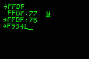
- Once the alternate ROM bank is selected, the "L" command for disassembly listings is available. Everything is just like you know it from the Apple II:
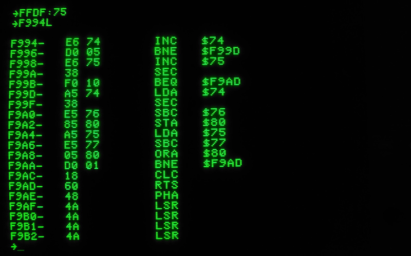
Works really well. And I'm really glad to finally have the builtin disassembler on the Apple ///.
I have a few more ideas and more ROM space is available. So more may be added...
My current "collection" of custom ROMs is available here:
Very nicely done! I almost didn't notice the rotated chip in your photo, LOL.
Well planned and executed. Great contribution and thank you for sharing!
Nice work!
You have been busy! The new adapter layout looks interesting. Do you need some kind of insulator between the eeprom socket pins and the 1K resistor that's just above the chip at C9? (Or does the eeprom straddle the bus bar - hard to tell from the angle of the picture.)
I added a couple of 90° jumper pins on my proto-board implementation to easily re-route pins 18 and 21 so it can plug into either the B9 rom socket or my eprom programmer, without the added height of a socket. Of course I only have a 4K eprom so can't take advantage of the bank 2 additions.
No, in my case the resistor lies flat on the PCB - so it's far below the top of the TTL IC next to it:
A3ROM_Resistor1k.jpg
Does that look any different on your board, i.e. was the resistor soldered standing upright on yours?
I was a little more concerned about the brown ground (or Vcc?) bar. But that is also a little lower than the TTL IC. And the adapter's PCB edge just stops before it. So also no threat of any of any pins making contact:
A3ROM_Bar.jpg
Concerning reprogramming, what I do is just remove the EEPROM from the adapter. This reduces the stress on the mainboard's socket, since I don't need to remove the adapter so often. Indeed, if the EEPROM was soldered to the PCB directly, then a much simpler PCB design was possible. But since I wanted the extra socket, which adds another 4mm to the whole stack, I needed this slightly more complex PCB, to move the EPROM further towards the rear.
My board has an identical layout (in this area, at least.) I was wondering more about the eeprom socket pins protruding from the bottom of the adapter board. Since the pins on my proto board that go into the B9 socket are virtually identical to IC pins, I wasn't too worried about stress on the socket. (This picture is an earlier version of the proto-board.)
img_001s.jpg
OMG!
I'm seeing a ROMX/// here. Perhaps if you used smd parts and could re-program in place, then a full-fledged product could be made. Yes the audience is rather small but if you decide to attempt this I could offer some pointers.
Hehe, reprogramming in place would be nice indeed. But with the Apple /// it's a feature which would probably interest much fewer people - only those like me, who want to work on the boot ROM themselves.
Otherwise, there is not just less Apple /// users out there: compared to the Apple II there is also less incentive to install a more sophisticated ROM replacement. The Apple /// ROM is just used for startup & diagnostics. That's why it's so tiny. There is no "language" ROM. And, unlike on the Apple II, most applications aren't using the ROM. They are all based on SOS, and SOS has its own drivers for everything - including disk + screen I/O. So, after the initial bootstrapping, the Apple /// ROM is basically unused.
Also, the Apple /// already has a programmable video character RAM. And an option to map a RAM to the ROM area, and enable write protection, so it behaves like a ROM. That's what it uses for "Apple ][ emulation mode", for example, where it's able to just load any Apple II ROM image (from a disk...), and then pretend it's in a ROM.