Hi all,
As some may not be aware of this, I started to work on cloning the Apple 1 prototype (aka Apple Computer A) since Nov'22 and here are how I did it and my observation.
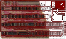
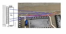
1. The gerber was created based on high res images of the original half piece, Newton board gerber with reference to schematic of production board and the old polaroid. Locations of components and traces follow the original as much as possible. (see the pic with gerber overlayed with image of the half piece)
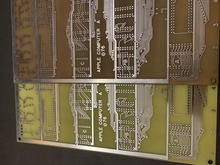
2. The board was likely made using double-sided FR1 material which has a brown color. The traces were coated with solder (HASL process) and edge connector was gold plated. Since double-sided FR1 is no longer made, I ordered sample boards based on the conventional FR4 material which has a yellow color. To create the brown color, I dyed the board using the Sharpie+Acetone rubbing trick.
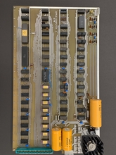
3. I did some research on the components used. The big orange capacitors are actually Sprague Atom 8000uf 16v (TVA1175.7) and 2000uf 25V (TVA1213). The blue coupling caps have a value of 0.47uf 25V (.47Z) from the auction photos and I painted the same caps I used for Newton NTI in blue. The silver caps are judged based on their sizes from the polaroids.
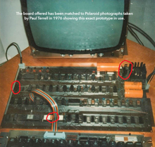
4. As for the assembly part, since all the traces follow the original, the same cuts and jumpers, which were done by Woz to the original board, are made to the replica board. Further to make the board compatible to ACI and Claudio (P-Lab)'s peripheral cards, I made additional jumpers and cuts as well: jumper from C to R (Pin 21), jumper from unregulated +12V / -12V to pin Y and Z, and cuts between -5V and pin Y, between -12V rail and pin 21 and between +12V and pin Z. These are critical as the prototype has slightly different edge connector X, Y, pin 21 pinout from the later production board but they are hidden under the edge connector. Below is the result.
Observations
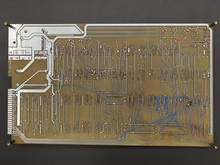
1. Judging from the images of the original board, it was quite likely that the board was designed and made around 6800 first as the "6800 only" area was populated and then the board was later modified for 6502 processor, as shown by the trace cuts leading to the "6800 only" area (I marked in red circle on the image of back side above) and jumper PIA-pin24 to +5V from the component side (which later became one of the "6502" jumper). In fact, the polaroid roughtly shows C1 7404 was populated and so likely the polaroids were taken when the board still held a 6501 (as it has gold cover rather than silver cover as seen in early MCS6502)
2. The -5V, +12V and -12V regulators are installed in different orientation as shown by the polaroid, all facing horizontally. The -12V also has a heatsink, may be it gets hotter than -5V and +12V.
3. Extensive jumpers and cuts were made to B5 74S257, which may be due to gerber design error.
4. The marking of 74154 pins doesn't use A, B, C, D and E but the output identification as shown in the schematic, so A was shown as 10, B as 11, C as 12, D as 13, E as 14 and F as 15.
To me, this is a dream comes true as when I first saw the polaroids few years ago, I wanted to clone the board as well, but since the image resolutions are too low and both Woz and Paul couldn't recall the details, I stopped the gerber work. It was long until this half piece original board showed up for auction and also thanks to Achim who gave me access to higher scan of the polaroid and the high res photos of the actual board from the auction, I have enough information to get this done. I would say it is more like a wall hanging talking piece, since it is less reliable than the later non-NTI and NTI board and it takes much more effort to build, I am not sure if there is much interest, but I can order a small run if there is enough interest there. I haven't had a quote on board made with gold-plated gold finger, but I assume without the soldermask and the board follows standard materials and process (vs the demanding Newton 1 and Newton NTI boards), the price tag will be lower (expect <$80 per board plus shipping). The board will come with a simple trace jumper / cut guideline. PM me if you are interested so that I can plan for one if feasible.
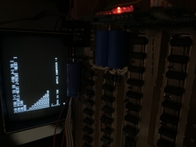
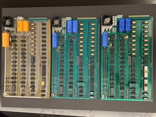
It is really nice to have Newton 1, Newton NTI and Newton-Byte in the same photo!
Hi Mike,
great job and a fantastic result, looks absolutely top notch.
Congratulations!
If you really set up a batch, I am definitely very interested in such a board and would take one of them from you immediately.That's awesome.
Thank you!
- Pete