Hi,
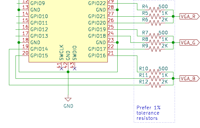
I wanted to add Mockingboard emulation functionality to the A2VGA-like board at the same time as the vga output. The first problem that needed to be solved was to free up several GPIOs for the right and left audio channels as well as for /IRQ control. As you know, in the standard A2VGA circuit all GPIOs are occupied, and I needed at least three free GPIOs. In the standard circuit 9 GPIOs are used to output the color code:
I thought that it would be possible to use two additional latches - one with store on the positive edge, the other on the negative edge clock signal. The result was the following diagram:
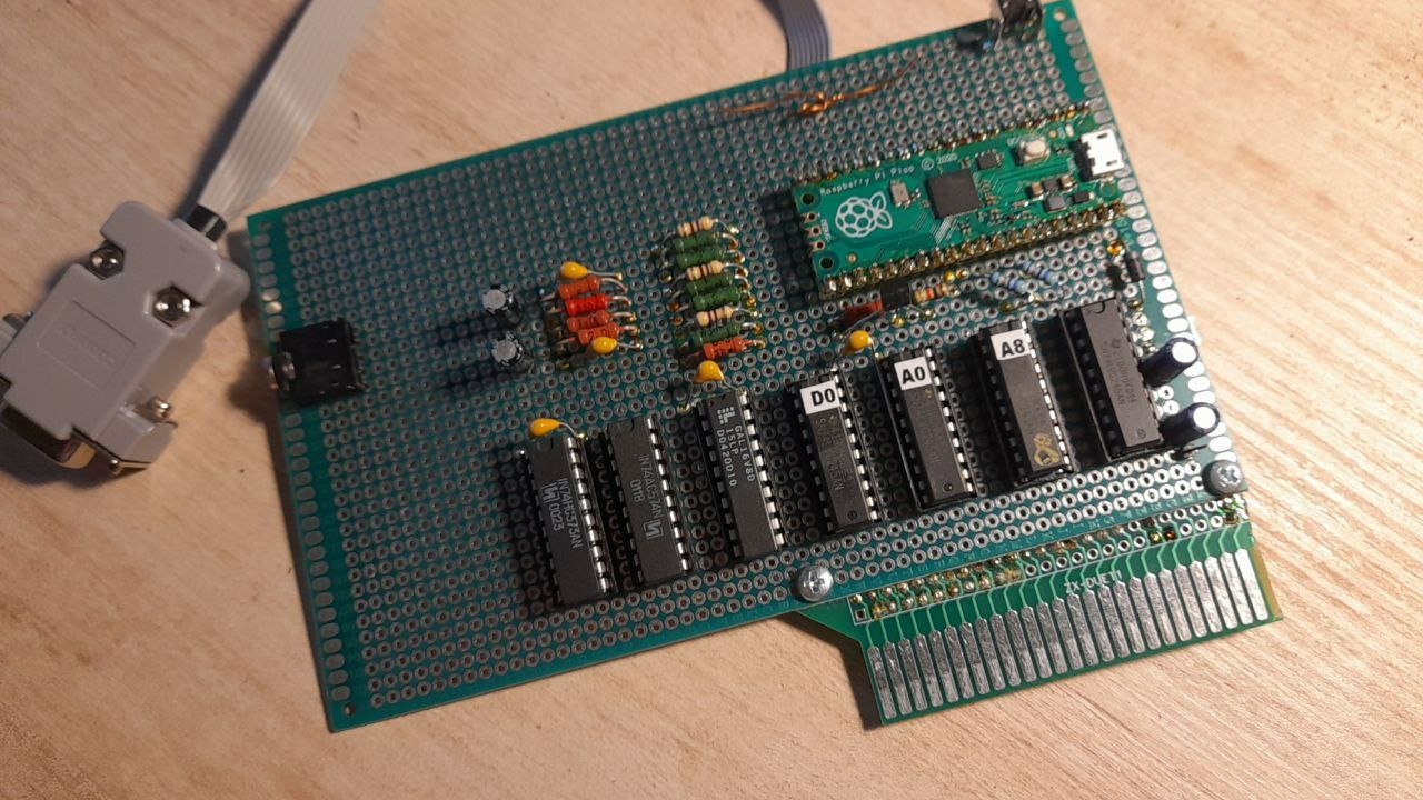
First 4 bits latched in HC373 at positive edge, then second 4 bit (with previos 4 bit from HC373) latched in HC574 at negative edge together with last 9 bit in GPIO18 with help side-set RP2040 PIO. Thus, 3 free GPIOs are released! Naturally, this circuit required changes to the firmware, in particular, doubling the vga-PIOs operating frequency and recalculating some timings in PIO blocks. If previously PIOs worked at a pixel clock frequency of ~25 MHz, then when sequentially loading values into two registers, a frequency twice as high is required - 50 MHz. This is most likely almost the maximum frequency for the 74hc IC series, so it is better to use something faster, for example, the 74AC series. In my case I used what I had on hand, namely 74HC374 and 74AC574:
The second problem is the lack of processor time to emulate two AY-chips at 44100Hz stereo PWM simultaneously with vga output, especially in high-resolution mode. If Pi Pico used to work at a frequency of 252Mhz, then I had to overclock the rp2040 to 378mhz. Fortunately, I've done this many times before and everything was fine. For audio output, two GPIOs are used with a low-pass filter according to a typical scheme:
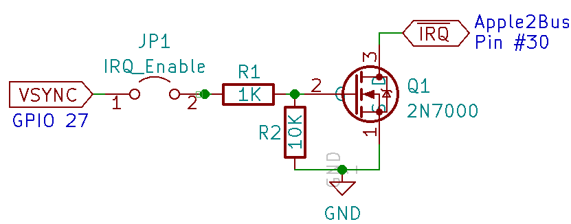
For proper Mockingboard emulation we also need drive/IRQ, so i used MacFly's a2vga mouse circuit (with different GPIO):
Unfortunately, I'm not very good at programming, so after a lot of very bad code practics, I got some results (short youtube video):
https://www.youtube.com/watch?v=K2fCMBh2t7I
So it almost works. I need to run additional tests.


Wow, keep up the awesome work!
Looking forward to seeing how this progresses.
Cheers,
Mike
What a nice project - well done!
Can this card be done for $100 or less?
What sound chip are you emulating? The AY-3-8913 has a bug in it according to French Touch.
I am using open-source library: https://github.com/digital-sound-antiques/emu2149 so its emulate AY-3-8910 or YM2149 i beleave. Currently i am chose AY-3-8910.
As I mentioned before, I'm not very good at programming, so I chose this library because I could make it work. But there's nothing stopping you from using another library, except for the need to figure it all out.
The cost of this card is about the same as any other A2VGA card, here only two latch chips, one transistor, several resistors and capacitors and a headphone jack are added.
Today i draw circuit and route PCB. Not finishing but alpha pre-view:
photo_2024-10-24_20-04-30.jpg
photo_2024-10-24_20-04-30 (2).jpg
Board size is 100 x 78 mm, so may fall under some promotions of PCB manufacturers (100x100 for $1 5pcs), the price should not be high i hope.
photo_2024-10-24_20-04-31.jpg
Looks great! If you need any help with testing I'd be happy to help you.
I received the first test boards and assembled one
photo_2024-11-19_14-51-54.jpg
photo_2024-11-20_12-01-19.jpg
The edge connector is slightly smaller than necessary in height, the margins from the edge are slightly smaller than necessary. Otherwise, the board is without errors. Clear image without jailbars. It is necessary to correct the board a little and then I will publish the project on github.
Since I don't know how this would work, does it need to go into a particular slot to work?I am thinking most Mockingboards (mine) go in Slot 4, tho you can also put one in slot 5 (or you can put two, one in each slot).So for sound to work, would that be the same? This card would go into slots 4 or 5 because the software looks for the cards there?
Yes, card need to be installed into slot #4 for mockingboard sound. Now the firmware has a hardcoded address corresponding to the fourth slot, but it can be changed to work in slot number five. Theoretically, you can try installing two cards - one in the fourth slot and the other in the fifth by changing the addresses in the firmware and it should work. But I most likely won't be able to check this in the near future, since I have a limited set of Apple II hardware - this is a replica of Apple II modified to Plus and a Dan II controller (prodos), so i limited to run Apple IIe/c software.
here we are https://github.com/Tronix286/a2vga_audio
Thank you Tronix. This looks really cool.
I was just wondering, as the Pico is dual core, if you dropped vga ... could you support two mockingboards on one card like a 12 voice Phasor?
A heads-up that because the card takes its input from the Apple II slot Bus, it is missing full analog signals and therefore works by reproducing what it sees on the bus into its internal frame buffer for output. This means that it does not show what appears on the screen exactly, but its own re-creation.
French Touch demos with cycle accurate mode shifting may not work correctly.
Alternate/Foreign character set (e.g. ROMX, //e alternate switch) ROMs will not be displayed if they are used (as the card will use its own character set).
If you have an Apple //e then a card that uses the AUX slot can access the analog signals and convert to VGA from there. e.g. Lukazi's A2VGA