Explore an AP-64, with and without firmware
| Attachment | Size |
|---|---|
| 140 KB |
There are a lot of AP-64 variants around, so let's explore this clone. Nexo Distribution sold it to me as "APX-EPROM-1" in March 1988.
First, here's a close look at the firmware socket and booster circuit.
Notice in the picture:
- The firmware socket is oriented with pin 1 toward the bottom edge, while all other ICs are oriented with pin 1 towared the top edge.
- Clone cards put variously different capacitors into C6 and C7. My card didn't have any capacitors there, which caused audible ringing noises to be emitted from the Apple speaker whenever the card was burning an EPROM. I installed two multilayer ceramic capacitors to eradicate the noises, although there might be a short-circuit risk because these capacitors are connected directly across the 5 volt power supply.
I installed the card in slot 5 for the following discussion.
To verify the card's expansion ROM, enter the monitor with the command CALL-155 to enter the monitor.
In the monitor, enter the commands CFFF C500 C800L
After pressing Return, it should list the contents of AP-64's expansion ROM at $C800 as follows:
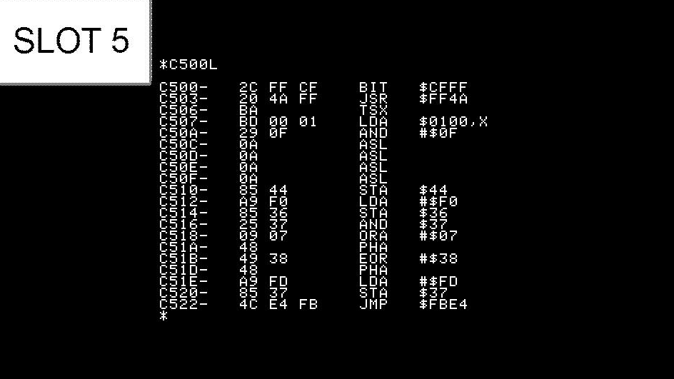
To check the bootstrap ROM, enter the command C500L and press Return. The card's bootstrap ROM should look like this:
If the firmware doesn't work properly, it is still feasible to operate the AP-64 via a program on the AP64r.DSK disk attached to this blogpost.
Step 1. With the computer turned off, configure the DIP switches for a 2732 EPROM, and make sure the AP-64 is installed in slot 5.
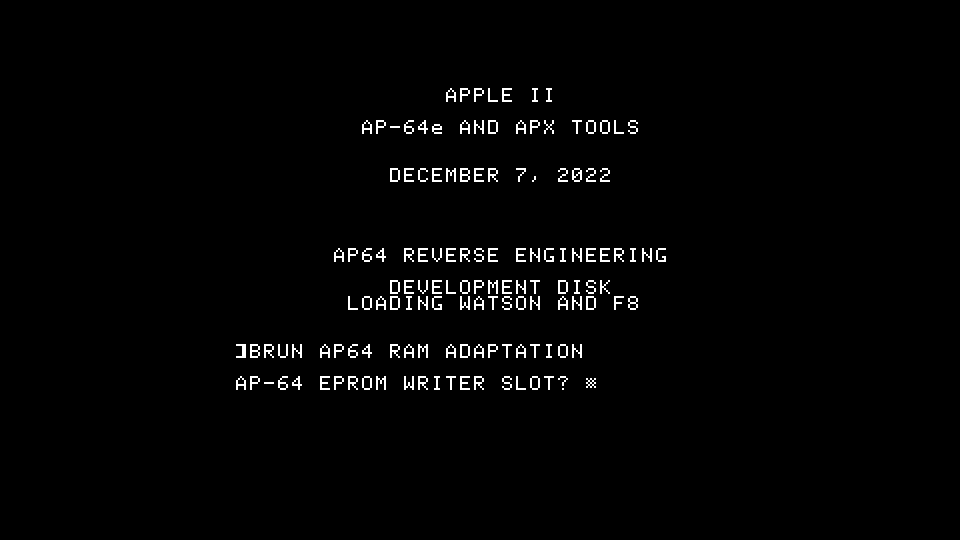
Step 2. Boot the AP64r disk.
Step 3. At the startup screen, type BRUN AP64 RAM ADAPTATION
Step 4. When the program asks "AP-64 EPROM WRITER SLOT?" enter 5.
The program will display the start screen and firmware version. (It's running from RAM, but the program is based on firmware 2.2)
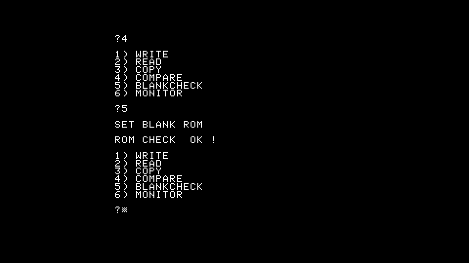
Step 5. Press 4 to choose EPROM type 2732
Step 6. At the menu enter 5 to choose the "BLANKCHECK" operation. This will cause the program to initialize the AP-64's 6821 interface adapter.
Step 7. With the ZIF socket empty press a key to run the blank check. The program should respond with "ROM CHECK OK !" because the empty ZIF socket behaves like an empty EPROM. (If it reports "ROM CHECK ERR !" then the hardware isn't working properly...or you chose the wrong slot.)
Step 8. Install a non-blank 2732 into the ZIF socket, oriented so that pin 1 is facing the top edge, and the bottom edge of the 2732 is located in the lowest holes of the socket. If you don't have a 2732, any pin-compatible ROM will do
(Because it's a 24-pin device in a 28-pin socket, there will be two empty rows at the top of the ZIF socket.)
Step 9: Press 5 to choose the "BLANKCHECK" operation again. Now, with a non-blank EPROM in the socke, it should report "ROM CHECK ERR !"
You can run further tests if you devise any. If you choose to "WRITE" to an EPROM, the program will attempt to write the entire ROM regardless of whether the hardware is working. (Even if you chose the wrong slot earlier.)
Another way to test the card is to read a pre-programmed ROM. The card can read the contents of any ROM that's pin-compatible with 2716, 2732 or 2764. For instance, you can try reading a 2316 or 2864 and compare the results against a known-good EPROM.
Or you could use the COMPARE function to compare a 2864 against itself (it should match) and run it again to compare it to an empty socket (it shouldn't match).
- S.Elliott's blog
- Log in or register to post comments


