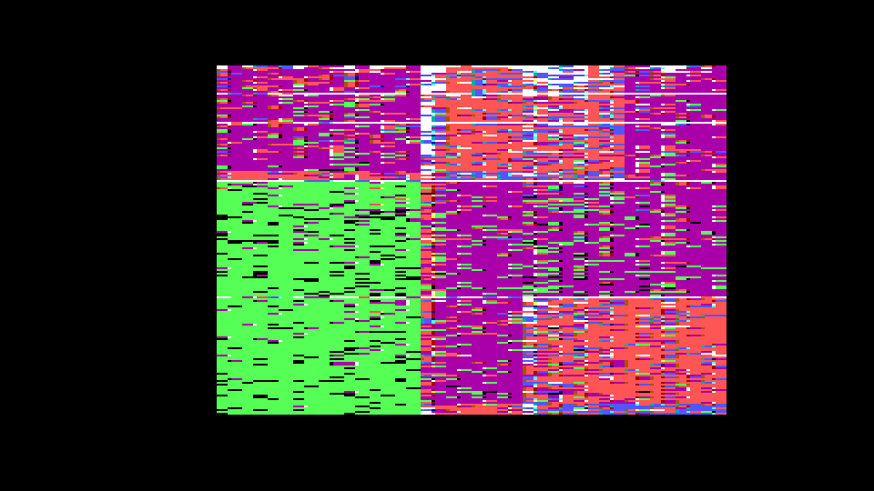
Clumsy (but pretty!) attempts to map video scanner's memory access
This discussion concentrates on Apple computers that use 60Hz video.
In his 1983 book Understanding The Apple II James Sather published detailed maps of the video memory accessed by the video scanner in the Apple ][ and Apple ][ Plus in order to display hires graphics. And he published similar tables for the Apple //e in his followup book Understanding the Apple IIe.
The data for the hires graphics screen occupies 8192 bytes of memor, of which 7680 bytes of data are transmitted as pixels and 512 bytes are "hidden" in non-displayed regions. The video scanner reads 17030 bytes of data from memory during each video frame, so some bytes are accessed more than once...even though they are only displayed one each.
How could I build a map of the hires screen to show how many times each byte is accessed during each frame?
I ran a series of experiments that attempted to count accesses one-column-at-a-time by plotting binary index-numbers in the hires graphics memory, then sampled the "vapor" from the video scanner and kept counts of how often each index appeared. Each column was sampled until the counters filled, then the program cleared the screen and repeated the procedure for the next column.
When all columns had been sampled, the program displayed a map colored to indicate how many times each byte had been accessed during each frame.
My first results were not very believable, especially the black ones in the two top rows, which implausibly suggests those pixels are displayed but never accessed.
The following picture showed a bias that caused each column to sample only-odd-rows or only-even-rows.
The next one added an spare index in a different column from the one being sampled.
Next I tried writing the samples directly into an Apple II Memory Expansion Card (aka: 'slinky') and counting them after enumerating 17030 locations in a 17-cycle loop, for a duration of exactly 17 video frames. I hoped that would eliminate the noise by capturing precisely one sample per position, but it massively intensified the noise. The memory-scanning patterns are visible through the noise, but it's a real mess!
I went back to the previous method, but eliminated branches within the sampling loop to ensure exactly 23-cycles per sample. (23 is a primitive root mod 17030)
Finally, it emitted a mostly-plausible map. Green pixels indicate bytes that are scanned only once per frame, which means the video scanner only reads them while it's actually drawing them on the screen. Purple bytes are those that are scanned twice, mostly during the horizontal blanking interval. Orange bytes are accessed three times -- the vertical column between the green and purple regions occurs because the video scanner doesn't increment the first address it reads during the horizontal blanking interval, so bytes in that column get accessed an extra time. Blue bytes are accessed four times or more during the vertical blanking interval, where the video scanner repeats the same six lines until the next video frame.
There are still a few suspicious details in that vapor map, such as an unexplained gap in the upper line of blue pixels, so I might tinker with it again.
- S.Elliott's blog
- Log in or register to post comments


Comments
Awesome investigation
Awesome investigation. I'd try this myself, but I no longer have a working display. My flat screen TVs don't like the Apple II video timing.
262 vertical scan lines * 65 cycles horizontal = 17030 cycles
1 scan line: HBL 25 cycles + HBL' 40 cycles
4550 cycle (70 horizontal scans) vertical blanking gate
I had to look up primitive root modulo n. I am also re-reading Understanding the Apple II from pages 5-7 onwards. *HBL and VBL are signals produced in the video generator. HBL (the horizontal blanking gate) is high during the right margin, horizontal retrace, and left margin of the Apple video display. VBL (vertical blanking gate) is high during the bottom margin, vertical retrace, and top margin of the Apple video display. Refer to Chapter 8 for more information about these signals.
If you want to use an Apple
If you want to use an Apple II with a flat panel display and it won't sync up on composite input you might try one of the composite to RGB or composite to HDMI converters. They aren't usually perfect, but a lot of them are "good enough".
Thanks. SUP 'R' MOD worked
Thanks. SUP 'R' MOD worked.
Here’s a photo of the flat panel and some messing with the video scanner:
https://postimg.cc/N5S5p4Qq
The first 5 columns are up 1 pixel from the rest of the line. Every 65 cycles there is a softswitch to/from LORES/HIRES in the 5th column. The Apple II plus does some funky stuff on the byte where the switch happens. There are FLASHing pixels but it's not in TEXT mode!
When I get a chance, I’ll run some of S.Elliott's programs.