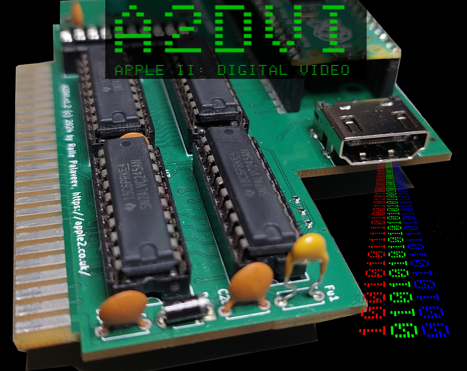
A2DVI: Apple II Digital Video Card
Video cards for the Apple II based on the PICO microcontroller are popular for a while now. They are cheap, consume very little power, and fit on a simple Apple II slot card. And they connect Apple IIs to modern displays. However, digital displays have conquered the world: their analog predecessors long since became retro devices themselves. Nowadays even analog VGA inputs are becoming rare. Which leads to the question: couldn't we make a PICO-based graphics card for the Apple II with a digital output instead? Use HDMI to replace the VGA connector? No more analog signal conversion required?
Spoiler: yes, we can! :)
The Challenge of (bit banging) Digital Video
A few months ago Ralle Palaveev contacted me. He had the idea to make a PCB prototype, combining the PICO-based "Apple II Analog VGA" design with an DVI/HDMI output. He sent me a board, asking if I wanted to look into creating the firmware...
The card connects the DVI's 8 differential signals to I/O pins of the PICO controller. DVI uses four channels, consisting of two differential signal pairs each: three channels for RGB data and one for a clock signal.
Generating a digital video stream may not seem more difficult than generating an analog VGA signal at first.
Just skip the analog conversion and send the data bits in raw, right?
Wrong! :)
Digital video is a challenge - when you're trying to "bit bang" the signal with a cheap general purpose microcontroller:
- The required frequencies and bit rates are insane. Analog VGA (at 640x480@60Hz) already has a pixel clock of over 25 MHz. The Apple II VGA cards were outputting 9bits per 25MHz cycle (3 bits per RGB channel). That was already mighty impressive, that the PICO could do that - just with "bit banged I/O". But a digital video stream (DVI) for the same resolution uses 8bit gray level values per RGB channel. Each is encoded into a 10bit "symbol" for transmission. Hence, DVI uses a clock which is 10x the VGA pixel clock, so over 250MHz. For all three data channels this adds up to 3x250mbit/s = 750mbit/s which the PICO needs to produce. And data always needs to be ready in time for each screen line, for each channel...
- Worse, DVI requires a protocol. Each symbol needs to be encoded before transmission. The correct encoding depends on what data was previously transmitted. The "TMDS" encoding scheme is simple - sounds like an exercise from a VHDL/FPGA programming course. Not difficult in an FPGA or ASIC design. But doing it in software on a tiny CPU, which only has a couple of clock cycles for each 3x10bits of data to be produced, in order to pressure-feed a DMA pipeline driving the PICO's I/O pins, which are guzzling data at a combined 750mbit/s, is a little tough - if not impossible.
Fun fact: since the software uses 16bit for each 10bit TMDS word, the PICO's RP2040 actually needs to produce 1.2 GByte/s. Pretty challenging for a tiny microcontroller, currently selling for just 70 cents, when bought in bulk (DigiKey).
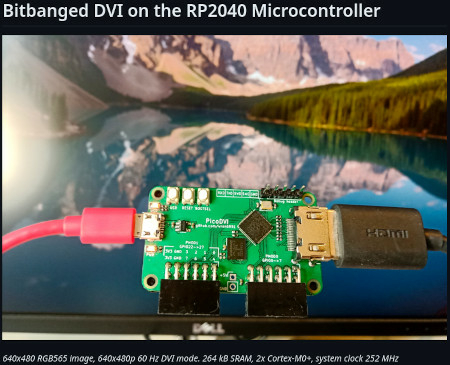
PicoDVI: It's actually possible!
There is an awesome open-source library "PicoDVI". Luke Wren, the author, generates a digital video stream on the PICO, using simple "bit banged" I/O - so no extra hardware required. Luke has implemented various modes for different VGA resolutions. Some use both CPU cores to produce a full resolution color image. He has squished and squeezed the PICO to make it possible. And he has applied an awesome trick to reduce - or even completely eliminate - the computation overhead required for the "TMDS" encoding. His trick works for monochrome modes, and for color modes at reduced (halved) resolution - simplifying the generation so much, that even a single CPU core of the PICO is sufficient.
But for A2DVI this wasn't quite enough: we only have a single CPU core to spare for video generation. The other core is already fully occupied with monitoring the 6502 bus. For some of the video modes the halved VGA resolution (320x240) was enough. But for HIRES (and other modes) we need both: full VGA resolution and color support.
However, while it seemed impossible at first, the Apple IIs limitations were helping: Apple II only has very few colors and a fixed color palette. This allowed to extend Luke's trick to also generate a full resolution color image, using a single CPU core only - limited to Apple II colors...
(More on the encoding tricks in the "bonus topic" below - for those really interested... :) )
So, here it is: A2DVI!
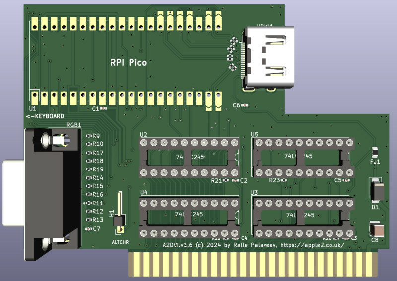
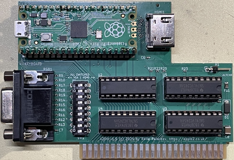
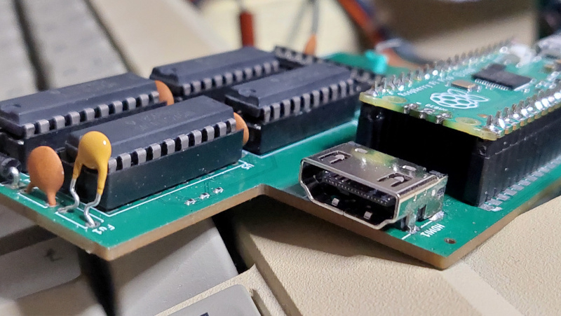
Hardware
- A2DVI uses 4 bus transceivers (74LV245) for 5V/3.3V conversion - an identical configuration to Mark Aiken's Apple II VGA card.
- It has an HDMI connector. The signal is actually DVI, however, DVI and HDMI use the same encoding, and HDMI 1.0 is backwards compatible to DVI. Of course, A2DVI uses an HDMI connector, since it's smaller, more convenient and much more common today.
- The PCB also has an option for an analog VGA connector. The HDMI+VGA connectors cannot be used at the same time. Ralle is experimenting with solder jumpers and DIP switches to select the active connector. Different firmware is required for VGA vs DVI: Mark Aiken's "Apple II VGA" firmware works with the VGA connector, while my new "A2DVI firmware" is required for DVI/HDMI output, of course.
- The PCB uses several SMD components - simple resistors and the HDMI connector. This saves space - and routing DVI's 250MHz differential signal pairs via through-hole resistors might not be such a great idea anyway...
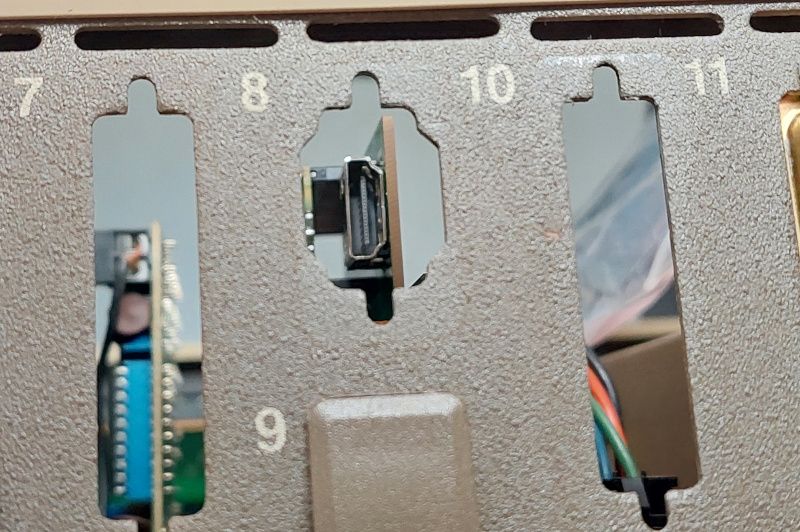
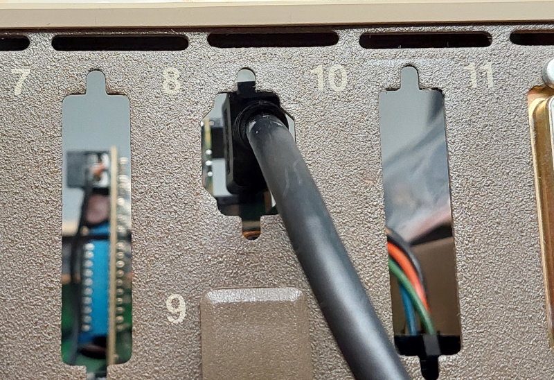
One advantage of the HDMI vs D-SUB VGA connector is, that the HDMI cable can be inserted through any of the Apple IIe's openings in the rear. However, since not all Apple IIe slots are aligned with the housing openings, you may need an HDMI cable which is a little flexible, depending on which slot you use:
Firmware
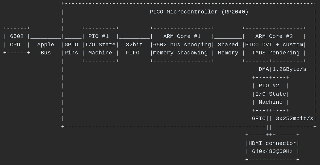
The firmware is based on a combination of the Apple II VGA firmware projects by Mark Aikens and David Kuder. The DVI signal generation is based on the PicoDVI library by Luke Wren. However, A2DVI uses custom rendering code, to convert the Apple II memory content to a "TMDS" bit stream directly - skipping the intermediate step of generating a VGA buffer for PicoDVI first.
Here's a brief look at the architecture:
Features of A2DVI
- Currently supports all standard Apple II + IIe video modes in color and monochrome: 40/80 column text, LORES, double LORES, HIRES, double HIRES.
- Supports Apple II, IIe and various clones (but neither Apple III, nor IIgs).
- Supports various languages and fonts.
- Dual language support using the "ALTCHR" language rocker switch of the Euro-Apple IIe (see below).
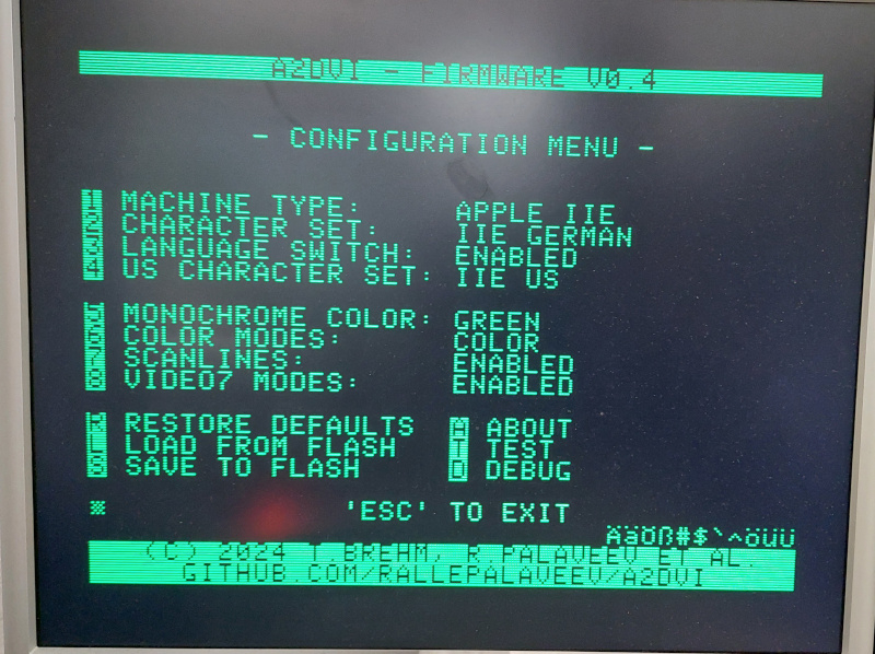
- Convenient menu, showing current configuration, and allowing instant changes - temporary or permanent.
- Can be installed in the normally unusable slot #3, even when the AUX/80 column card is present.
- Low power consumption/heat dissipation: <70mA@5V = 0.35W
A2DVI Dual-Language Support
A2DVI is "designed in Europe", so of course comes with proper dual language support... :) A feature that not all Apple II fans in the US may fully understand (nor care about :D ). The "Euro IIe" machines support two languages: the US character set is fixed and common to all machines, while the second character set depends on the country's language. Since there were no unused characters in Apple II's character set, Apple had to repurpose standard characters, like square and curly brackets, and map them to language specific characters instead.
Yes, this was a terrible solution by today's standards - you couldn't have brackets and language-specific characters at the same time. For example, when programming, you needed brackets as a syntax element (e.g. in Pascal), but when the program contained text in German/French/..., you needed the local character set when editing those. So editing source code required frequent toggling between the two. But back in the 80s, everyone was happy about a machine which at least somehow supported multiple languages.
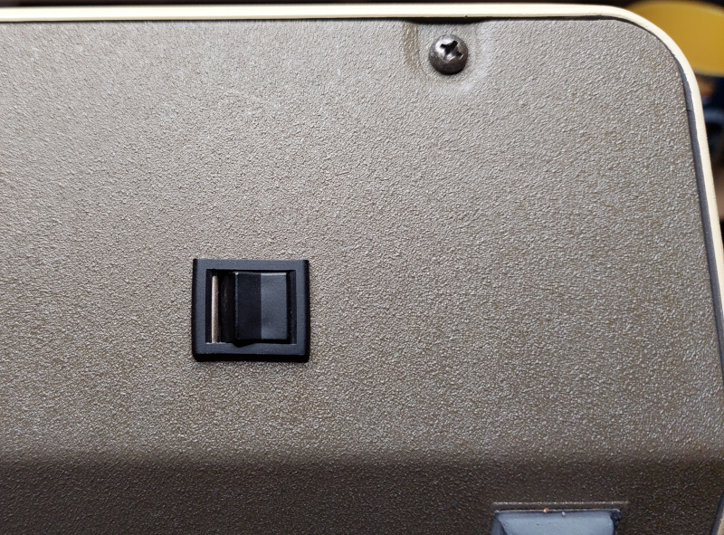
To mitigate the hassle of switching character sets, Apple added a little rocker switch to the keyboard, so users could instantly toggle between local and US character set. The switch also toggles the keyboard mapping between US and the country's local standard:
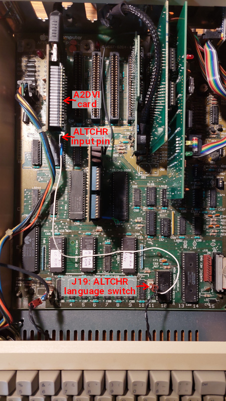
A2DVI now has support for the "language rocker switch". This requires an optional wire to be installed, since there is no other way to determine switch state - which directly controls the mainboard's video + keyboard ROMs. The extra wire connects an input on the A2DVI card to the mainboard's "ALTCHR" signal - available at J19, or directly at the keyboard rocker switch. The switch state is what allows A2DVI to properly emulate the video ROM's language switching behavior:
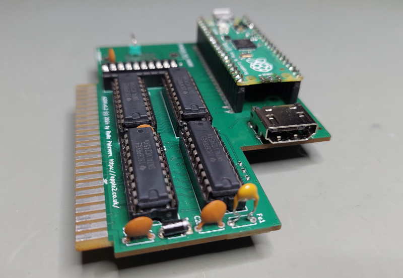
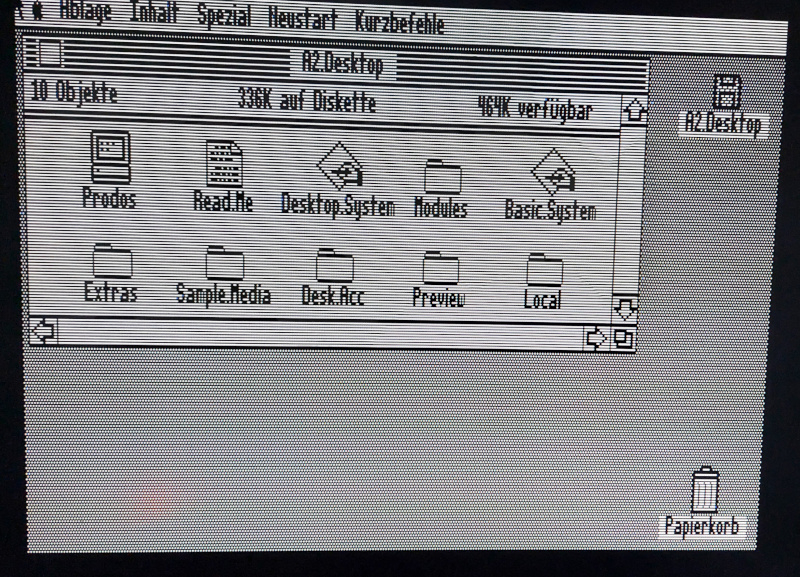
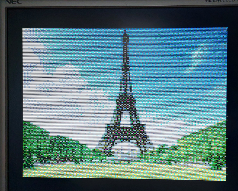
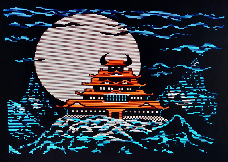
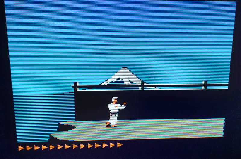
Photos
A a few photos showing A2DVI at work.
Yes, I know you cannot tell from blurry photos whether that's an analog or digital signal source - or just an emulator. But, trust me... :D
Current Project Status
The A2DVI firmware is almost complete - all standard video modes are implemented. A few more things are to be done, but we've reached a point were we could do with a little more testing.
The Gerber files for the PCB and firmware aren't online yet (July 2024). They will be in a few weeks. Ralle is still experimenting with different PCB variants and making changes to the PCB design. However, he already has a batch for testing. If you're interested in helping with testing the new design in one of your Apple IIs, then let us know - or post in this discussion thread:
To details, have a look at these GitHub projects:
The PCB Gerber files and matching firmware builds will be available shortly, once initial testing is complete.
Bonus Topic: "TMDS" Signal Encoding with PICO. Let's Balance Some Bits!
For those who want to dive deeper, here is a litle bonus topic. As described above, generating a digital video signal is a little tough, when all you have is software running on a general purpose microcontroller - and just a handful of clock cycles per pixel.
DVI/HDMI's "TMDS" encoding scheme ("Transition-Minimized Differential Signaling") uses a 10bit encoding for every 8bit of data. TMDS has two goals:
- Reduce the number of bit transitions (1->0, 0->1), to reduce electromagnetic interference (EMI). TMDS achieves this by selecting between two different encoding schemes, depending on which works best - in reducing the number of bit transitions.
- Generate a true AC signal: an electric signal without any DC component. In order to be "true AC", the number of "1" and "0" bits transmitted over each data channel must be equal - on average. The TMDS protocol achieves this, yet again, by selecting between two further encoding variants: a normal and an inverted scheme. The video generator has to keep track of the current bit balance (how many "1" and "0"s were sent so far), and consider the bit balance of the next symbol to be transmitted. Again, the best encoding option must be chosen.

This is not difficult. But especially the second property requires the software to do calculations, to make decisions depending on what was sent before, and to adjust to the protocol on the fly. Not realistic with a couple of CPU cycles per pixel.
Luke, the creator of the PicoDVI library, solved this with an awesome trick: by reducing the effective resolution by half, duplicating each transmitted pixel. Slightly simplifying: he always transmits the first pixel using the normal encoding, and the second using the inverted encoding. The result is a perfect double pixel, which has a "perfect bit balance". The data is guaranteed to contain exactly as many "1" bits as "0" bits. This means the code no longer needs to keep track of the bit balance - it always in perfect balance anyway. Even better: the transmission no longer depends on what was sent before. Data can also be hard-coded or stored in a fixed table. All the CPU still has to do is copy & concatenate the data for each double pixel. Doesn't get any easier and faster than that!
Luke's trick also worked for full resolution monochrome modes, where adjacent pixels only use gray levels of 0x00 or 0xFF. However, it doesn't work for images with arbitrary/random RGB data.
The halved resolution worked great for Apple's low resolution modes (LORES, 40 column text). However, for higher resolutions the halved resolution wasn't enough. However, since the Apple II only supports a very limited number of colors, I found a way to generalize Luke's trick. I made a little Python script which considered every possible two-pixel combination that we need for the higher resolutions. The script tries to find an encoding for each possible two pixel combination, which is perfectly "bit balanced". Sometimes it just works. Sometimes it's necessary to slightly tune the color values - often a +/-1 does the trick. Sometimes slightly larger adjustments were necessary. The script finds the best options, puts them in a table - and now the PICO all has to do is copy the data from the table.
"You tweaked the RGB values to eliminiate the TMDS calculation overhead? Dirty tricks?! That's cheeeeeating!!!"
Yes, it is! And it works much better than I ever had expected! :D
Thanks!
As mentioned before, this project is based on the work and contributions of others. Thanks to Mark Aikens and David Kuder for their work on the analog VGA projects. And thanks to Luke Wren for his PicoDVI library!
Apple II Forever!
Thorsten Brehm, Ralle Palaveev, July 2024
- MacFly's blog
- Log in or register to post comments
Comments
There's a discussion in a
There's a discussion in a separate thread.