and here the details
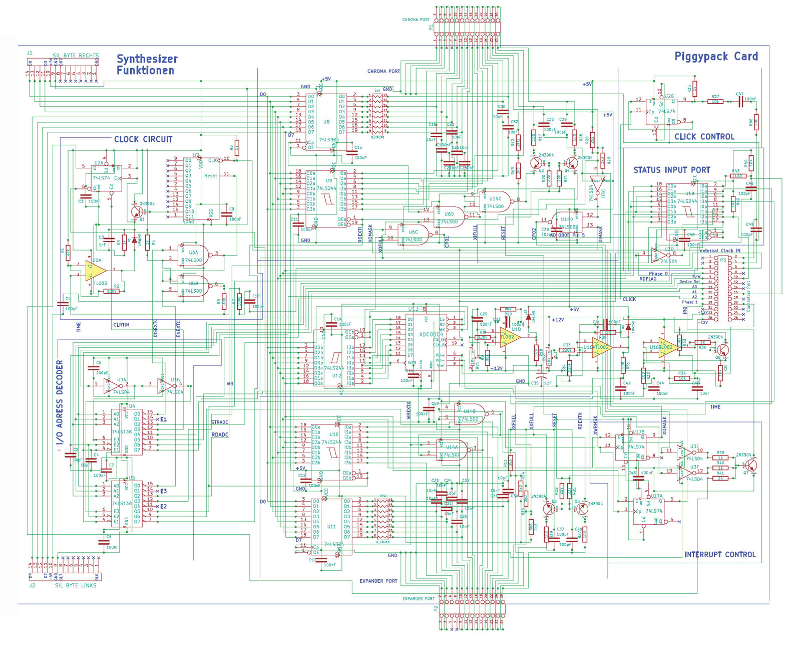
of the first Piggyback card ( the synthisizer interface ):
the circuitplan of the piggyback card 1:

Here the component layout:

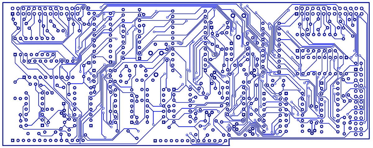
the layer of the componentside:

the layer at the solderside:

and here is the view of both layers ( component- and solderingside )
combined:

And now lets take a look to the second "piggyback"card that shall
interface the Apple II series of computers with MIDIO-devices.
This "Piggyback2" MIDI Interfacecard will be made as a single board and
then before soldering and populating the PCB - it shall be
cutted apart in the Piggyback2 card and a smaller part of the PCB which
we might call the MIDIconnector card. It supplies the Apple
with 2 MIDI-Output ports and 2 MIDI-Input ports ( which permits to work
with 2 channels and therefor is designed for use in
stereo mode.
While the "Piggyback2"
card shall be plugged to the maincard the MIDIconnector card may
stay outside of the computer with itīs
plugconnectors and connected by using a flatribbon cable that is plugged
to the so called Chroma connector on the card. Due to the fact,
that this connector is just a "loopthrough" connection from the
piggyback card to external devices and performing communication
between the external devices and the Apple II by the use of the
maincard.
Here is the view of the population of the "piggyback2"MIDI card:

and here is the layer at the soldering side:

here is the view of the componentlayer:

here is the view to
the combination of both layers:

and here is the view to
the circuitplan of the "piggyback"2 MIDI connector board:

|